Key takeaways
- Every PV conductor must pass two tests. A wire that passes only one is too small.
- In our seven example cases, derating set the size three times, the 125% test twice, and both agreed twice.
- A combiner output of 54.00 A passes derating at 6 AWG but needs 4 AWG for the 125% test.
- Four strings in one conduit pass the ampacity and derating tests at 14 AWG when the conduit sits above the roof, but check the string fuse first: a typical 20 A fuse for four parallel strings exceeds the 15 A small-conductor cap on 14 AWG, which pushes the real answer to 12 AWG or larger. On the roof surface, the same conduit needs 10 AWG regardless.
- Voltage drop is a separate check. It can force a larger wire than ampacity does.
To see which permit-set tools size conductors for you, see the best solar permitting software.
Wire and conductor sizing at a glance
Conductor sizing asks one question: will this wire stay within its temperature rating at the worst current and the worst conditions? Two ampacity tests answer it.
| Item | Detail |
|---|---|
| Formula | Test 1: terminal-column ampacity ≥ 1.25 × maximum circuit current. Test 2: 90°C ampacity × ambient factor × conduit adjustment ≥ maximum circuit current. String current is 1.25 × Isc. |
| Unit / typical range | Amperes. Copper 14 AWG is 20 A in the 75°C column and 25 A in the 90°C column (Southwire, LugsDirect). |
| Where it matters | Plan-set conductor schedules, plan review and inspection. |
| Standard or rule | NEC 690.8(B) with the 310.15 correction tables and 110.14(C) for terminals, as the secondary sources in Sources describe them. We did not open the NFPA text, so check the clause numbers in your edition. The edition your AHJ adopts decides (see NEC 690). |
| In software | Permit-set tools size wire from equipment and the AHJ’s edition. Design tools often show only voltage drop. |
Why does conductor sizing matter for installers?
Wire that is too small overheats. Wire that is too large wastes copper. Standard plan forms ask you to show the result for each circuit.
The City of Colton’s standard plan asks you to compute each circuit’s maximum amps, then fill a table of allowed amps. It says the table number "shall not be less". Ampacity and voltage drop are separate checks, and a size can pass one and fail the other, so each needs its own check.
How do you size a PV conductor?
Find the maximum current, run two tests, then take the smallest listed size that passes both. These steps combine the methods in GreenLancer, Mike Holt (EC&M) and IAEI.
- Find the maximum circuit current. A string is module Isc × 1.25. Parallel strings add. For AC, use the inverter’s continuous output current from its nameplate (EC&M).
- Test 1: multiply by 1.25. Read the table column for the equipment terminal rating, 60°C or 75°C, with no derating (IAEI). The size’s value must reach the result.
- Pick a design ambient. Add the rooftop adder if it applies. Read the ambient factor from the 90°C column. EC&M uses that column for correction with PV wire.
- Count current-carrying conductors in the raceway. Read the conduit adjustment factor.
- Test 2: multiply the 90°C table value by both factors. It must reach the maximum current from step 1.
- Take the smallest listed size that passes both tests. Do not pick a size between rows.
- Size the overcurrent device and check voltage drop separately. IAEI sets the device at 125% of continuous current, rounded up to the next standard size in most cases. LugsDirect flags 14, 12 and 10 AWG with a small-conductor overcurrent note (240.4(D)), which applies to the device size.
The two 125% factors have different jobs: one is on Isc and one is on the conductor test, so a string needs 1.56 × Isc in total. The NEC 690 page explains them. The calculator also caps the derated value at the terminal-column value, to respect the terminal limit that IAEI describes under 110.14(C). In our cases test 1 already clears it, so the cap changes no size.
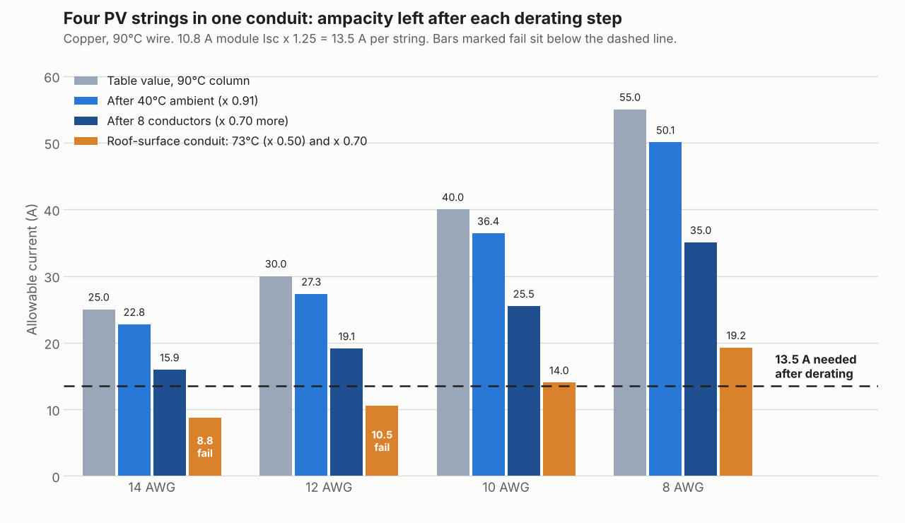
Figure 1. Four strings in one conduit pass at 14 AWG until the roof adder applies. Then 14 and 12 AWG fail, and 10 AWG passes with 14.0 A against 13.5 A.
Worked example: string, combiner and AC feeder
Seven cases show which test decides. The last column names the test that set the size. We assume a 10.8 A module Isc, four strings, a 40°C design ambient, 90°C copper wire and 75°C terminals. The inverter is 7.6 kW at 240 V, rated 32 A continuous.
Ampacities are Table 310.16 copper values. Ambient and adjustment factors are the 2020 NEC’s, as Elliott Electric prints them. Your adopted edition may differ. Roof-surface cases add 33°C to 40°C, so 73°C. The adjustment factors are 0.80 for 4 to 6 conductors and 0.70 for 7 to 9.
| Case (max current) | Test 1: 125% | Ambient × conduit factor | Test 2: required 90°C ampacity | Size, and deciding test |
|---|---|---|---|---|
| A1 One string, conduit above roof (13.50 A) | 16.88 A: 14 AWG | 0.91 × 1.00 | 14.84 A: 14 AWG | 14 AWG, both agree |
| A2 One string, conduit on roof (13.50 A) | 16.88 A: 14 AWG | 0.50 × 1.00 | 27.00 A: 12 AWG | 12 AWG, derating |
| B1 Four strings, one conduit, above roof (13.50 A) | 16.88 A: 14 AWG | 0.91 × 0.70 | 21.19 A: 14 AWG | 14 AWG on ampacity alone, but see the fuse check below |
| B2 Four strings, one conduit, on roof (13.50 A) | 16.88 A: 14 AWG | 0.50 × 0.70 | 38.57 A: 10 AWG | 10 AWG, derating |
| C Combiner output, four strings (54.00 A) | 67.50 A: 4 AWG | 0.91 × 1.00 | 59.34 A: 6 AWG | 4 AWG, 125% test |
| D1 AC feeder, 32 A inverter (32.00 A) | 40.00 A: 8 AWG | 0.91 × 1.00 | 35.16 A: 10 AWG | 8 AWG, 125% test |
| D2 AC feeder, two circuits, hot attic (32.00 A) | 40.00 A: 8 AWG | 0.71 × 0.80 | 56.34 A: 6 AWG | 6 AWG, derating |
Test 2 shows the ampacity the 90°C column must offer: max current divided by both factors. The roof cases use 73°C and the attic case 60°C for the ambient factor.
The 60°C column is from LugsDirect (2020) alone. We did not use 3 AWG or 1 AWG, because only one source printed them. None of the seven cases needs them.
Case C shows why both tests matter. Test 2 alone allows 6 AWG: 75 A × 0.91 is 68.25 A against 54.00 A. But test 1 needs 67.50 A in the 75°C column, and 6 AWG offers 65 A there. So the size steps up to 4 AWG.
Case D1 is similar. The 125% test needs 40.00 A. 10 AWG (35 A) cannot give that, so the answer is 8 AWG. The 40 A overcurrent device is a separate step. The three-line diagram page shows an AC run with the same factors.
Case B2 turns on the roof adder. At 73°C (x 0.50) and eight conductors (x 0.70), 14 AWG gives 8.75 A and 12 AWG gives 10.50 A, both below 13.50 A. 10 AWG gives 14.00 A. With 60°C terminals instead, A1 and B1 would move from 14 to 12 AWG. The other five cases keep their sizes. Module or equipment instructions can set a minimum size. The Colton form uses 12 AWG.
Case B1’s 14 AWG answer passes the ampacity tests, but check the overcurrent device before wiring it that way. Four parallel strings normally need a string fuse at the combiner, sized at 1.56 times the module’s rated Isc per NEC 690.9(B), which for this page’s 10.8 A Isc is about 16.9 A, rounding up to a 20 A fuse. A 20 A overcurrent device on 14 AWG copper conductors fails the small-conductor cap at NEC 240.4(D), which limits 14 AWG to 15 A regardless of what the ampacity tables allow. So a real four-string, one-conduit circuit needing a 20 A string fuse should go to 12 AWG (capped at 20 A under 240.4(D)) or larger, not 14 AWG, even though 14 AWG clears the ampacity and derating math above. Run this check for your own module’s Isc and fuse size before using 14 AWG on more than two parallel strings.
For a three-phase feeder with a neutral, see the three-line diagram page.
What changes the answer, and where do sources differ?
These inputs move the result, and the sources do not agree on all of them. Your AHJ decides each of them.
- Method: the Colton form uses a single 1.56 multiplier on Isc, a different method from the two separate tests here.
- Edition: our ambient and adjustment factors are 2020 NEC values from one printer. Southwire labels its ampacity table 2023 and the ratings match LugsDirect’s 2020 table.
- Roof adder: GreenLancer says to add 33°C (60°F) for raceways close to the roof. It puts the limit at under 7/8 in for the 2017 and 2020 NEC, and under 3/4 in for 2023. West Coast Code Consultants (March 2024) uses 7/8 in and says the adder table was removed. A Citrus Heights standard plan on the 2013 California code lists ampacity by height above the roof instead.
- Counting conductors: GreenLancer counts the positive and negative of each string, so four strings make eight. It does not count the equipment grounding conductor. GreenLancer is the only source we read that says this, so confirm it with your AHJ.
- AC circuits: sources disagree on the section. IAEI (2011 NEC) ties the inverter’s rated-output current to 690.8(A)(3). West Coast’s 2020 NEC slides give conflicting section numbers for the maximum-current step and state the 125% AC rule under 705.12. GreenLancer contradicts itself. SolarAPP+ states the 125% rule for inverter output circuits.
- Terminal rating: GreenLancer says most solar equipment has 75°C terminals. IAEI’s examples use 60°C and 75°C. IAEI says unmarked terminals default to 60°C for circuits of 100 A or less or 14 to 1 AWG. Read the label on each device.
PV conductor ampacity calculator
Enter the circuit, conductor count, ambient and terminal rating. The calculator runs both tests and shows each size’s pass or fail.
How solar software handles conductor sizing
Solargraf and SolarAPP+ document wire sizing for ampacity, and Aurora documents conductor sizing without naming ampacity. None of the four pages read describes the full method.
| Software | Sizes conductors for ampacity? | How / where | Notes |
|---|---|---|---|
| Solargraf | Yes | Permit settings: wire temperature rating, default 90°C or 75°C, "directly affects wire sizing and ampacity calculations". Next breaker size recalculates wire sizes. | Help article, 19 March 2026. The page does not mention derating or conduit fill. |
| SolarAPP+ | Yes | Calculates wire size, with "code required ampacity adjustments based on site conditions indicated by the contractor". | Technical FAQ (undated). The inspector checks conduit fill in the field. The contractor supplies calculations on request. |
| Aurora Solar (Instant Plan Sets) | Partly | NEC 2026 page: Instant Plan Sets "apply the 2026 code to conductor and overcurrent protection sizing". The circuit table lists terminal rating, maximum wire temperature and conductor count. | Pages updated 8 October 2026 and 27 January 2026. Neither says ampacity or describes the method. US pitched roofs up to 25 kW AC, no three-phase. |
| HelioScope | Not stated | "Optimize conductor sizes" recalculates wire distances and shows STC voltage drop beside each conductor. | Help article, 9 July 2025. No ampacity, NEC or derating wording on the page. |
All four rows were read in October 2026. Not stated means the company page we cite does not say. Partly means the page covers conductor sizing but not ampacity. For a ranked comparison of permit-set tools, see the best solar permitting software list.
Common mistakes with conductor sizing
FAQs
Why does PV wire need two 125% steps?
The two factors do different jobs, so both apply. GreenLancer calls the first the enhancement factor, applied to module Isc. The second is the continuous-load factor, applied to the conductor’s ampacity. The NEC 690 page shows the combined multiplier.
Does the ground wire count toward conduit fill derating?
In GreenLancer’s example, no. It does not count the equipment grounding conductor, but it does count each string’s positive and negative. No other source we read says this, so confirm with your AHJ. Neutral rules for inverter circuits are on the three-line diagram page.
Which table column do I use, 75°C or 90°C?
Both, for different tests. Test 1 uses the column for the equipment terminals, 75°C in our example. Test 2 starts from the 90°C column, then applies the ambient and conduit factors. Read each device’s label for its terminal rating. IAEI says unmarked terminals default to 60°C for circuits of 100 A or less or 14 to 1 AWG.
Does conduit on the roof need the temperature adder?
Yes, it can. GreenLancer ties it to a distance above the roof, and that distance differs by edition in its text. West Coast Code Consultants says the table was removed. The AHJ decides which rule it enforces.
Does voltage drop change the wire size?
Yes, it can. A long run may need a larger wire than ampacity alone allows. Size for ampacity first, then check voltage drop, and take the larger result.
Related terms
- Voltage drop calculation: the resistance maths that checks a size for energy loss.
- NEC 690: the code article that sets the 125% rules.
- String sizing: choosing modules per string, which sets the current.
- Three-line diagram: the drawing that shows every conductor and its size.
Next step: run your own circuit through both tests in the calculator above, then shortlist plan-set tools that carry conductor sizes from the best solar permitting software.
Sources
- Code method. GreenLancer, NEC 690.8 conductor sizing (27 August 2026). Mike Holt, EC&M, July 2016 (edition not stated). John Wiles, IAEI Magazine, 2011 NEC. West Coast Code Consultants, Solar PV Plan Reviews, 6 March 2024 (2020 NEC). The NFPA NEC text itself is not a source for this page.
- Tables. Southwire SPEC 45411 (2023 NEC Table 310.16). LugsDirect, Table 310.16 (2020). Elliott Electric, ambient factors and adjustment factors (2020 NEC).
- AHJ forms. City of Colton, Solar PV standard electrical plan (undated). City of Citrus Heights, Solar PV standard electrical plan (2013 California Electrical Code).
- Software. Solargraf settings. SolarAPP+ technical FAQ. Aurora: NEC 2026 and Instant Plan Sets. HelioScope, Optimize conductor sizes.
All sources checked October 2026. Last updated 30 October 2026. Next scheduled review: 30 January 2027.