Key takeaways
- For DC and single-phase AC, drop = 2 × current × resistance per length × one-way length. Three-phase uses 1.732 in place of 2.
- At 10 A, 400 V and 100 ft, copper drops 1.57% on 14 AWG, 0.99% on 12 AWG and 0.62% on 10 AWG.
- Aluminium has about 1.6 to 1.65 times copper’s resistance (resistivity: 1.58, OpenExamPrep’s Table 8 column: 1.65). So the same size drops about 60% more.
- Drop falls with current. At half the current, the drop percentage halves (0.31% against 0.62% here).
To work out your own run, use the calculator below. To see which design tools print the drop on each wire run, see the best solar design software.
Voltage drop calculation at a glance
Voltage drop is current times the resistance of the whole circuit. You show it in volts and as a percentage of the circuit voltage.
| Item | Detail |
|---|---|
| Formula | DC and single-phase AC: drop = 2 × I × R × L. Three-phase: 1.732 × I × R × L. L is one-way length. R is resistance per unit length at conductor temperature |
| Targets in the sources cited | 3% branch circuit, 5% combined (NEC informational notes, as described by Mayfield Renewables and OpenExamPrep). 2% DC and 1% AC (Penn State). Under 1% desirable, 2% maximum on DC (Huawei) |
| Where it matters | Cable size, energy loss, string mismatch, plan-set conductor tables |
| Standard or rule | Resistances come from NEC Chapter 9 Table 8 as printed in a published sample (see Sources) |
| In software | Design and plan-set tools show it per wire run. Some pick the cable size from a limit |
Why does voltage drop matter for installers?
Voltage drop wastes energy as heat. A long run on thin wire can pass 3% (Figure 1).
Huawei’s PV Tech article says a high DC drop also widens the voltage spread between strings on one MPPT. That raises mismatch loss.
Bigger wire lowers the drop but costs more. This page does not cover ampacity. For that, see wire and conductor sizing.
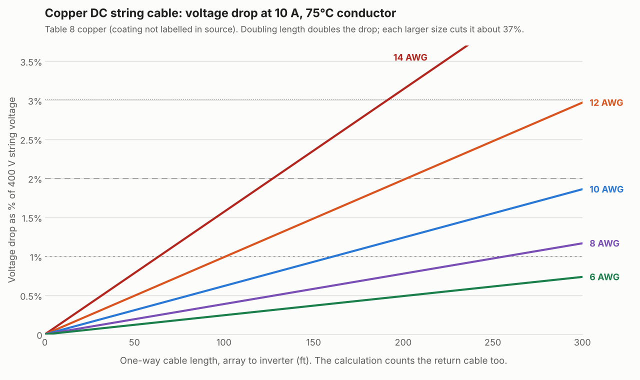
Figure 1. At 10 A on 400 V, 14 AWG copper reaches 2% drop at about 127 ft one way. For 12 AWG it is 202 ft and for 10 AWG it is 323 ft. Reference lines mark 1%, 2% and 3%.
How do you calculate voltage drop on a DC string or AC run?
Multiply current by the resistance of the full out-and-back conductor length. Then divide by the circuit voltage. The five steps below work for DC and for small AC runs.
- Take the current. Penn State’s notes use the module operating current (Imp) for DC source circuits. For AC, use the inverter’s rated output current.
- Take the one-way length from array to inverter. DC and two-wire AC use both conductors, so the loop is twice that length. Penn State says this for DC.
- Look up resistance per length. NEC Chapter 9 Table 8 lists uncoated copper 10 AWG at 1.21 ohm per 1,000 ft for solid conductor and 1.24 ohm per 1,000 ft for stranded, the small difference coming from the stranding, not from a coated-versus-uncoated split. The Mike Holt sample page prints the stranded row (1.24). OpenExamPrep’s table shows the solid row (1.21). Match the row to the conductor you are actually pulling, then correct for conductor temperature.
- Multiply: drop (V) = 2 × I × R × L ÷ 1,000. R is ohm per 1,000 ft. L is feet.
- Divide by the reference voltage and compare with your target. For DC, Penn State uses the string’s maximum-power voltage (Vmp). For AC, use the nominal voltage.
For balanced three-phase, use 1.732 in place of the factor 2 (OpenExamPrep). This is a resistance-only method. It ignores reactance and power factor on AC.
How do copper, aluminium and temperature change the result?
Aluminium drops about 1.6 to 1.65 times as much as copper at the same size. A hotter conductor drops more.
- Material: HyperPhysics lists resistivity of 1.68e-8 ohm metre for copper and 2.65e-8 for aluminium at 20°C, a ratio of 1.58. OpenExamPrep’s Table 8 aluminium column gives about 1.65 (10 AWG 2.00 against 1.21, 8 AWG 1.26 against 0.764). So one size up is not quite enough: 8 AWG aluminium (1.26 ohm per 1,000 ft) is slightly worse than 10 AWG copper (1.21) in that same table. Aluminium needs a little more than one size up, and ampacity is a separate check.
- Aluminium on the 250 ft DC run: at 6 AWG it would drop about 1.01% against 0.61% for copper, using our calculator’s 1.64 estimate.
- Temperature: Table 8 resistances are at 75°C. Note 2 corrects them with R × [1 + 0.00323 × (T − 75)] for copper. For aluminium it uses 0.00333. A 3°C rise adds about 1% to resistance. For 10 AWG copper the factor is 1.048 at 90°C and 0.855 at 30°C.
- Datasheet cables: Prysmian’s Slim Solar Twin PV sheet lists maximum resistance at 20°C for tinned copper. It is 5.09 ohm per km (4 mm²) and 3.39 (6 mm²). At 70°C the factor is 1.196, using a copper coefficient of 0.00393 per °C (HyperPhysics).
Using 75°C for a cooler cable gives a cautious answer. A cable in hot conduit may run hotter. Check your own conductor temperature.
What voltage drop target should you use?
The sources disagree. Treat each figure as a recommendation, and confirm with your AHJ, the inverter maker and the client contract. None of the figures in the sources is a PV-specific limit.
| Source | Figure | Applies to |
|---|---|---|
| NEC informational notes, as described by Mayfield Renewables and OpenExamPrep | 3% branch circuit, 5% combined with feeder (attributed to the NEC) | General circuits. Recommendation only |
| Penn State AE 868 course notes | 3% total (attributed to the NEC). 2% DC plus 1% AC | Course recommendation |
| Huawei, PV Tech, October 2022 | Under 1% desirable. 2% not exceeded | DC cables in PV plants |
| Aurora PV system losses e-book | 2% wiring loss for most systems. 1% with thicker wire or short runs | Loss assumption in modelling |
| Easy PV FAQ | Picks the smallest cable giving under 1% drop | Easy PV’s cable-selection rule |
Mayfield Renewables (pv magazine USA, 2020) calls 2% a long-held rule of thumb with anecdotal origins. It finds no firm 2% requirement in the NEC. It adds that later code references treat the notes as if they were requirements. So check the edition your AHJ enforces. Its modelling shows the rule no longer fits most commercial and utility projects.
Worked examples: DC string, AC run and metric cable
A 10 A DC string on 400 V loses 0.62% in 100 ft of 10 AWG copper. Over 250 ft it needs 8 AWG to stay near 1%. Each row is computed from the formula.
DC string. Current 10 A, string voltage 400 V, copper at 75°C, Table 8 resistances. The loop is twice the one-way length.
| One-way length | Size | Loop resistance (ohm) | Drop (V, %) | Within 1% / 2%? |
|---|---|---|---|---|
| 100 ft | 14 AWG | 0.628 | 6.28 (1.57%) | No / Yes |
| 100 ft | 12 AWG | 0.396 | 3.96 (0.99%) | Yes / Yes |
| 100 ft | 10 AWG | 0.248 | 2.48 (0.62%) | Yes / Yes |
| 250 ft | 10 AWG | 0.620 | 6.20 (1.55%) | No / Yes |
| 250 ft | 8 AWG | 0.389 | 3.89 (0.97%) | Yes / Yes |
| 250 ft | 6 AWG | 0.245 | 2.46 (0.61%) | Yes / Yes |
AC run. Single-phase 240 V, 30 A, 120 ft one way, copper at 75°C, resistance only.
| Size | Drop (V) | Drop (%) | Within 1%? | Within 3%? |
|---|---|---|---|---|
| 10 AWG | 8.93 | 3.72% | No | No |
| 8 AWG | 5.60 | 2.33% | No | Yes |
| 6 AWG | 3.54 | 1.47% | No | Yes |
Metric cable. DC string, 10 A, 400 V, 50 m one way (100 m loop), tinned copper. Resistance is the maker’s maximum, corrected from 20°C to 70°C.
| Size | Loop resistance at 20°C (ohm) | Drop at 20°C | Loop resistance at 70°C (ohm) | Drop at 70°C |
|---|---|---|---|---|
| 4 mm² | 0.509 | 5.09 V (1.27%) | 0.609 | 6.09 V (1.52%) |
| 6 mm² | 0.339 | 3.39 V (0.85%) | 0.406 | 4.06 V (1.01%) |
If you use the one-way length in the DC formula, you get 1.24 V for the 100 ft, 10 AWG case instead of 2.48 V.
On the AC run, 8 AWG passes a 3% target at 2.33% but misses 1%. For the inverter’s voltage window, see string sizing. To see where the run sits on the drawing, see the three-line diagram.
Does peak voltage drop equal the energy you lose?
No. The drop is highest at full current, and few hours reach it. So annual energy loss is smaller than the headline figure. Mayfield reports that about 3% of daylight hours in Phoenix, 0.47% in Atlanta and 0.11% in Seattle reach 1,000 W/m².
In our example the drop falls from 0.62% at 10 A to 0.31% at 5 A and 0.124% at 2 A. Module current roughly follows irradiance. Mayfield’s modelling used 400 W modules, 1,000 V and 1,500 V string inverters and code-minimum 12 AWG wire. It found effective DC wire losses of 0.223% to 0.592% across its sites. That leaves out hours when the inverter limited power. It is a model, not a measurement.
Higher string voltage helps too. At the same 4,000 W and cable, a 600 V string carries 6.7 A instead of 10 A. Its drop percentage is 44% of the 400 V figure. See system losses for where wire loss sits in the loss chain.
Voltage drop calculator
Enter current, voltage, length, material, size and temperature. It gives the drop in volts and percent against your target.
How solar software handles voltage drop
All five tools below report voltage drop on company pages read in October 2026, and only Easy PV states a limit (under 1%).
| Software | Calculates or reports voltage drop? | What it shows |
|---|---|---|
| Aurora Solar (Instant Plan Sets) | Yes | Drop per wire run in the plan set |
| PVcase Roof Mount | Yes | Drop for the whole string, both cables |
| HelioScope | Yes | Drop at STC next to each conductor |
| Easy PV | Yes | Smallest cable with drop under 1% |
| Solargraf | Yes | Listed among its SLD and three-line calculations |
- Aurora Solar (Instant Plan Sets): The circuit table lists voltage drop. A setting adds circuit length and voltage drop per wire run to the conductor table on sheet PV-3. Aurora help page, updated 27 January 2026. No percentage limit stated on that page.
- PVcase Roof Mount: Release notes say the drop is determined for the whole string, including both the negative and positive cables. It also suggests cable cross-sections on the SLD. PVcase release notes 1.40.1, no release date shown.
- HelioScope: Shows the STC voltage drop next to each conductor and recalculates wire distances when equipment moves. HelioScope help, updated 9 July 2025. Calculation method and limit not described.
- Easy PV: Picks the smallest cable cross-section with a drop under 1% of the voltage across the cable, using IEC 60228 / BS 6360 resistances. Easy PV FAQ, no absolute date shown. Temperature and length basis not stated.
- Solargraf: A company blog lists voltage drop among its SLD and three-line tool calculations, with copper and aluminium. Blog only, undated.
Design tools that show drop per wire run are ranked in our list of the best solar design software. For larger sites, see the best commercial solar design software.
Common mistakes with voltage drop calculation
FAQs
What is an acceptable voltage drop for solar DC cables?
No single limit is mandatory for PV. The sources cite 3% (NEC informational note for branch circuits), 2% (Penn State, Huawei’s maximum) and under 1% (Huawei’s preference, Easy PV’s tool default). Confirm the target with your AHJ and equipment maker.
Is 2% voltage drop required by the NEC?
No. Mayfield Renewables says the NEC contains no firm 2% requirement for PV. Penn State’s notes say the NEC does not require the calculation and recommends a maximum of 3%. Your adopted code edition and AHJ decide what applies.
Do I use one-way or round-trip length?
Use the loop length in the resistance. It is twice the one-way run for DC and two-wire AC. Balanced three-phase uses 1.732 times the one-way run instead. Penn State’s notes say this for DC and single-phase AC. PVcase Roof Mount states that it counts both the negative and positive cables.
Does aluminium need a bigger size than copper?
For the same drop, yes, by a little more than one size. In OpenExamPrep’s table, 8 AWG aluminium (1.26 ohm per 1,000 ft) is slightly worse than 10 AWG copper (1.21). That is a study-guide estimate, so use the maker’s aluminium table, and check ampacity separately.
Related terms
- Wire and conductor sizing: choosing conductor size from current, derating and voltage drop.
- String sizing: choosing how many modules go in series and parallel.
- NEC 690: the US code article for PV wiring and safety.
- Watt, volt and amp: the three units that describe a circuit.
Next step: run your longest string through the calculator, then see which tools print drop per wire run in the best solar design software. For commercial string and feeder runs, see the best commercial solar design software.
Sources
- Penn State AE 868, "Voltage Drop" (checked October 2026).
- Mayfield Renewables, "Analyzing the 2% DC voltage drop rule", pv magazine USA, 30 September 2020 (checked October 2026).
- Mike Holt sample PDF: NEC Chapter 9 Table 8 copper resistances (14 to 6 AWG) and note 2 coefficients (checked October 2026). The copper figures come from this sample, not from NFPA’s own text, and show the stranded uncoated row. The edition is not stated.
- EC&M, "How to Use Chapter 9 in Your Next Design": 8 AWG at 75°C and the note 2 formula (checked October 2026).
- OpenExamPrep, "Conductors, Resistance, and Voltage Drop": three-phase formula, 3% and 5% wording, aluminium ratio (checked October 2026).
- Prysmian, Slim Solar Twin PV datasheet (checked October 2026).
- HyperPhysics, resistivity and temperature coefficient at 20°C (checked October 2026).
- Huawei, PV Tech, 28 October 2022 (checked October 2026).
- Aurora Solar, PV system losses e-book, DC losses (checked October 2026).
- Aurora Instant Plan Sets help (checked October 2026).
- PVcase Roof Mount release notes 1.40.1 (checked October 2026).
- HelioScope, Optimize conductor sizes (checked October 2026).
- Easy PV FAQ (checked October 2026).
- Solargraf SLD and TLD blog (checked October 2026).
Last updated 30 October 2026. Next scheduled review: 30 January 2027.