Key takeaways
- Grounding is the US word for a connection to the earth. Earthing is the UK and IEC word.
- There are two jobs. Equipment grounding bonds exposed metal. System grounding ties one circuit conductor to that bonded system and to earth.
- The 2012 paper describes 25 ohms or less for one electrode. Your AHJ’s adopted code sets the target.
- Invented example: a 16 mm rod in 100 ohm-metre soil gives 33.5 ohms at 3 m and 18.6 ohms at 6 m. In 300 ohm-metre soil, 12 m still gives 30.7 ohms.
- Fall-of-potential tests put the inner stake at about 62% of the way to the outer stake (Metrel, citing IEEE 81-2012). Fluke’s own table uses 60 to 67%.
To keep test records that prove bonding, see the best solar commissioning software.
Grounding and earthing at a glance
Grounding connects metal to the earth. In some designs it also connects one live conductor. Judge it by bonding continuity and by resistance to earth in ohms.
| Item | Detail |
|---|---|
| What it is | A deliberate connection to earth. US papers say grounding. IEC-based documents say earthing. |
| Two jobs | Equipment grounding (bond all exposed metal) and system grounding (tie one circuit conductor to it), as Wiles (2012) describes them. |
| Typical numbers | Electrode: 25 ohms or less (2012 paper). Sensitive equipment: 5.0 ohms or less (Fluke Calibration). Bonding conductor: 4 mm² or more (Nordmount). |
| How it is tested | Earth resistance with stakes or clamps. Bonding continuity with a low-resistance tester. |
| Standard or rule | Your AHJ’s adopted code. Nordmount cites HD-IEC 60364-7-712 for array bonding. |
| In software | Design tools list conductor sizes. Test software reports instrument data. See the software table. |
Why does grounding matter for installers?
Grounding conductors appear in plan-set circuit tables. Commissioning must prove the bonding. You may not see a weak connection until a fault happens.
Nordmount says the installer must measure and document bonding continuity before commissioning. Wiles says electrode resistance is rarely measured because it needs specialized equipment. He adds that, as of 2012, many local codes, particularly in the dry Southwest, require two grounding electrodes always. Check your local code, because this comes from his 2012 paper.
For what opens on a fault, see overcurrent protection and arc-fault protection. This page covers the earth connection those devices need. It does not cover ground-fault detection on ungrounded arrays. For conductor sizes, see the wire and conductor sizing page.
What do grounding, earthing and bonding mean?
Grounding and earthing name one idea in two regions. Bonding joins metal parts so they sit at one potential.
| Term | Meaning | Source |
|---|---|---|
| Grounding / earthing | The overall idea of connecting a system to the earth. A secondary guide maps the NEC word "grounding" to the IEC word "earthing". | Anern guide, updated April 2026 |
| Equipment grounding | Bonds (electrically connects) all exposed non-current-carrying metal parts. | Wiles, October 2012 |
| System grounding | One current-carrying conductor is bonded to the equipment grounding system, which also gives the connection to earth. | Wiles, October 2012 |
| Equipment grounding conductor (EGC) | "The conductors used to bond the various exposed metal surfaces together" are EGCs. | Wiles, October 2012 |
| Grounding electrode conductor (GEC) | The conductor that connects to a grounding electrode in contact with the earth. | Wiles, October 2012 |
Then the electrode, bonding and ungrounded terms.
| Term | Meaning | Source |
|---|---|---|
| Bonding / equipotential bonding | Joins metal parts so they sit at one potential. Nordmount asks for a conductor of at least 4 mm² per array, to an inverter earthing bar. | Nordmount document, undated |
| Grounding electrode | "The metallic device used to make contact with the earth". | Wiles, October 2012 |
| Grounded PV system | "A PV system is defined as a grounded system when one of the DC conductors (either positive or negative) is connected" to the grounding system. | Wiles, October 2012 |
| Ungrounded array | Allowed when the NEC 690.35 requirements are met. Inverters designed for ungrounded systems need no grounding electrode conductor. | Wiles, October 2012 |
An ungrounded array drops system grounding only. The frames still need bonding. Wiles says that before the 2005 NEC, one DC conductor had to be grounded above 50 V. A 1994 Sandia paper says the US and Canada required grounding. It says Europe and Japan opted for an essentially ungrounded system. Rules have changed since that paper.
Nordmount adds that a clamped steel structure is not bonded just by delivery. Assembly does not bond it either. You must check continuity after correct installation and torque.
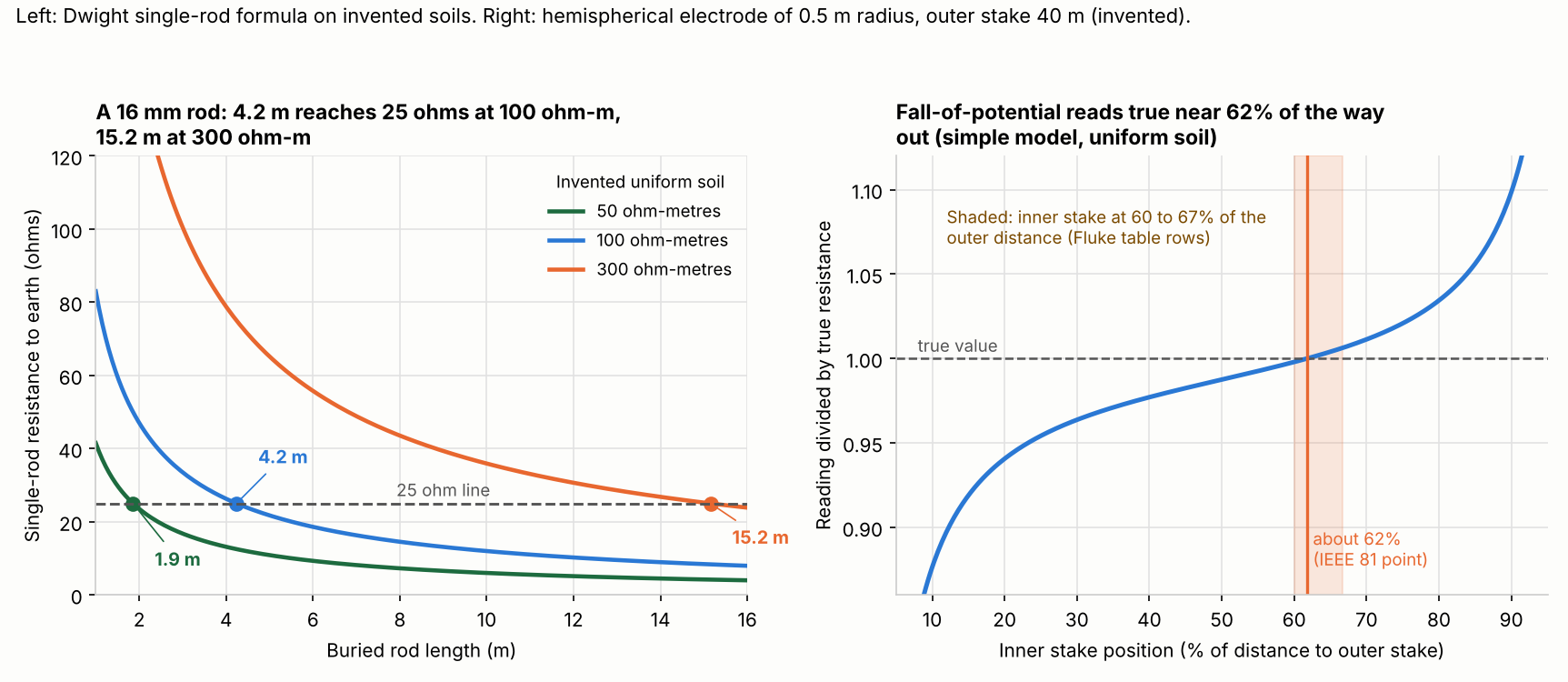
Figure 1. In example uniform soil, rod length sets whether one rod reaches 25 ohms: 4.2 m at 100 ohm-metres, 15.2 m at 300. In the simple model, a fall-of-potential reading is true near 62% of the way to the outer stake.
How do you measure earth resistance and bonding?
To measure earth resistance, pass a known current through the electrode. Probes in the soil read the voltage. Check bonding on its own, with a low-resistance continuity tester.
Fluke describes the fall-of-potential method this way.
- Disconnect the electrode from the site. Connect the tester to it.
- Drive two stakes in a straight line away from the electrode. Fluke says 20 m (65 ft) is normally enough.
- The tester sends a known current from the electrode to the outer stake. It reads the voltage at the inner stake. Then it applies Ohm’s law.
- Move the inner stake 1 m either way and read again. Fluke gives a 30% change as the threshold. If readings differ by more, widen the spacing.
Metrel puts the inner stake at 61.8% of the way from the electrode to the outer stake. It cites IEEE 81-2012, Annex C. Its model assumes equal currents, uniform soil and hemispherical electrodes. Fluke’s table sets the stakes by electrode depth. The last column is our own sum.
| Electrode depth | Inner stake | Outer stake | Inner as share of outer |
|---|---|---|---|
| 2 m | 15 m | 25 m | 60.0% |
| 3 m | 20 m | 30 m | 66.7% |
| 6 m | 25 m | 40 m | 62.5% |
| 10 m | 30 m | 50 m | 60.0% |
Fluke Calibration names four methods. They are stakeless, selective, soil resistivity and fall of potential. It calls the stakeless clamp method preferred when parallel grounds exist and stakes are hard to drive. It gives no pass limit for it.
A four-pin Wenner test gives soil resistivity. Megger prints the formula as 2πaR. Here a is the pin spacing and R the tester reading. Megger calls it "average soil resistivity to a depth equal to the probe spacings".
For bonding, the Fluke SMFT-1000 page lists a protective conductor resistance range of 0.00 to 19.99 ohms. Resolution is 0.01 ohm. Test current is at least 200 mA. The page lists no electrode resistance test.
Does one rod reach 25 ohms? A worked example
One rod reaches 25 ohms only in low-resistivity soil. Soil of 100 ohm-metres needs a rod about 4.2 m long. Soil of 300 ohm-metres needs about 15.2 m. These figures are example and modelled. Rod resistance uses the Dwight formula as EEPower prints it. R = ρ / (2πL) × (ln(4L/a) − 1), with a the rod radius. All inputs are example. The soil is assumed uniform.
| Case | Soil (ohm-metres) | Wenner reading (2 m spacing) | 16 mm rod, buried length | Modelled resistance (25 ohms or less?) |
|---|---|---|---|---|
| A | 100.0 | 7.96 ohms | 2.4 m (8 ft) | 40.4 ohms (No) |
| B | 100.0 | 7.96 ohms | 3 m | 33.5 ohms (No) |
| C | 100.0 | 7.96 ohms | 6 m | 18.6 ohms (Yes) |
| D | 300.3 | 23.9 ohms | 3 m | 100.6 ohms (No) |
| E | 300.3 | 23.9 ohms | 6 m | 55.8 ohms (No) |
| F | 300.3 | 23.9 ohms | 12 m | 30.7 ohms (No) |
In high-resistivity soil the practical route is a second electrode, or another electrode type. When one electrode does not meet 25 ohms, Wiles describes a second one more than six feet away.
The formula matches EEPower’s own example. Our sum gives 34.7 ohms for a 3 m rod in 100 ohm-metre soil. The rod is 12.7 mm wide. EEPower states about 35 ohms. Doubling the length cuts resistance by about 45%. Raising the diameter from 12.7 to 19.05 mm cuts it by just 6%.
EEPower also warns that frozen upper layers raise resistivity sharply. A reading in one season is not a design value for all seasons. The 25 ohm line is an input here. It is not a rule for your site.
Ground rod resistance calculator
It repeats the table for your own values. The defaults are example.
How solar software handles grounding
Of the two software tools and one hand tester below, only Aurora’s Instant Plan Sets lists a grounding conductor size ("EGC size" in the circuit table). None documents electrode resistance. The Fluke tester page covers bonding resistance only.
| Tool | Handles grounding? |
|---|---|
| Aurora Solar (Instant Plan Sets) | Partly |
| Solargraf | Not stated |
| Fluke SMFT-1000 with TruTest Solar | Partly |
Partly: Aurora lists a conductor size, and Fluke lists a bonding resistance test, but neither covers electrode resistance. Not stated: the company page we cite does not say.
- Aurora Solar (Instant Plan Sets): The Circuit Table list includes "EGC size". The help page does not mention grounding electrode conductors, bonding or electrode resistance. No date shown. Checked October 2026.
- Solargraf: The SLD and three-line diagram post (no date shown) and the permit settings article (19 March 2026) do not mention grounding, earthing, EGC, GEC or bonding. Checked October 2026.
- Fluke tester with TruTest Solar: The tester page lists protective conductor resistance and says it works with TruTest data management software. It lists no earth electrode resistance test. No date shown. Checked October 2026.
Tools that draw the single-line diagram carry the conductor sizes. See the best solar SLD software. For test reports, see the commissioning and test report page.
Common mistakes with grounding
FAQs
Is earthing the same as grounding?
In practice, yes. US documents say grounding, and IEC-based documents say earthing. Both name a deliberate connection of a system to the earth. Details differ by code, so follow your AHJ’s adopted edition.
What is the difference between equipment grounding and system grounding?
Equipment grounding bonds exposed metal. System grounding bonds one circuit conductor to that system. An ungrounded array has no system grounding. Bonding means electrically joining metal parts.
What resistance should a ground rod have?
The target is 25 ohms or less for one rod, pipe or plate electrode. Wiles (2012) cites NEC 250.53(A)(2), and a 2023 NEC quote in an ECM code quiz places the 25 ohm exception there too. Fluke Calibration cites 250.56 for 25.0 ohms. Confirm the section in your AHJ’s adopted edition. Fluke Calibration also says NFPA and IEEE recommend 5.0 ohms or less. We did not read those documents.
Do ungrounded PV arrays need earthing?
The frames still need bonding. Nordmount’s IEC-based document asks you to bond the support structure. That applies where bonding is required. It also asks you to measure continuity before commissioning.
Related terms
- Overcurrent protection: the fuse or breaker that opens on excess current.
- Arc-fault protection: detecting an arc in DC wiring and stopping the current.
- DC disconnect: the switch that opens the DC circuit.
Next step: measure the installed electrode and the bonding, then store the results with a tool from the best solar commissioning software list.
Sources
- J. C. Wiles Jr., Photovoltaic System Grounding, Solar America Board for Codes and Standards, October 2012 (distributor copy) (checked October 2026).
- Nordmount, Functional Earthing and Equipotential Bonding, undated (checked October 2026).
- Fluke, Fall-of-Potential Measurement, undated (checked October 2026).
- Fluke Calibration, Four methods to conduct earth ground testing, undated (checked October 2026).
- Metrel, Earth resistance measurement and 62% rule, undated (checked October 2026).
- Megger, Let’s get technical: soil resistivity testing, 26 August 2014 (checked October 2026).
- EEPower, How to Improve Resistance to Ground, 25 September 2020 (checked October 2026).
- ECM, Code Quiz: Single Electrode Resistance (quotes the 2023 NEC 250.53(A)(2) Exception) (checked 30 October 2026).
- Sandia, Analyses of grounded and ungrounded photovoltaic power systems, 1 July 1994 (checked October 2026).
- Fluke, SMFT-1000 PV tester product page, undated (checked October 2026).
- Anern, Grounding/Earthing Standards Differences, updated 24 April 2026 (checked October 2026).
- Aurora Solar help, Instant Plan Sets, undated (checked October 2026).
- Solargraf, permit-ready SLD and three-line diagram tool, undated and Solargraf permit settings help article, 19 March 2026 (checked October 2026).
Last updated 30 October 2026. Next scheduled review: 30 January 2027.