Key takeaways
- One 430 W module prints 59.7 V and 8.91 A at standard test conditions. Its Voc is 64.71 V at -10 °C and 53.25 V at 70 °C.
- Isc follows sunlight: 1.78 A at 200 W/m² and 8.91 A at 1,000 W/m². Temperature moves it by only 0.04% per kelvin.
- Cold Voc, not the 25 °C value, sets the string length. Under a 600 V ceiling at -10 °C the example fits 9 modules, not 10.
- Isc x 1.25 is 11.14 A for this module. That equals its current at 1,250 W/m² if current scales in a straight line.
- A sign slip on the coefficient gives 54.69 V, not 64.71 V, at -10 °C. That allows 10 modules at 600 V, one too many.
To check cold Voc against string limits in software, see the best solar design software.
Voc and Isc at a glance
Both are datasheet values at standard test conditions (STC). Voltage peaks when cells are cold. Current peaks in strong light.
| Item | Detail |
|---|---|
| Formula | Voc(T) = Voc at STC × (1 + β × (T − 25)), with β negative. Isc(T, G) = Isc at STC × G ÷ 1,000 × (1 + α × (T − 25)), with α small and positive. |
| Unit / typical range | Volts and amps. Example datasheet: 59.7 V, 8.91 A, β −0.24 %/°C, α +0.04 %/°C. PVEducation gives about −2.2 mV/°C for a silicon cell and +0.06%/°C for Isc. |
| Where it matters | String length (cold Voc), circuit current (Isc x 1.25) and field test readings. |
| Standard or rule | The datasheet’s STC is air mass 1.5, 1,000 W/m² and 25 °C. Code limits and factors are on the NEC 690 page. |
| In software | Design tools warn when temperature-corrected Voc passes a limit. None of the five tools we checked documents an Isc check (see the table below). |
Why Voc and Isc matter for installers
Cold Voc decides how many modules fit in a string. Isc sets the current used to size circuits. Get either wrong and a design fails review or runs past a component’s limit.
Voltage is highest when cells are cold and the sun is bright. So designers correct Voc to a low temperature instead of using the 25 °C value. The NEC 690 page covers which voltage limit applies and where the design low comes from. The inverter side is on the string sizing page.
Current works from the rated Isc. John Wiles wrote in IAEI Magazine, posted 5 January 2018 (November/December 2017 issue), about the 2017 NEC. He calls the first 125% a safety factor for extra dc output. He says the irradiance peak "may approach 1250 W/m2". He adds that a second 125% may apply because the current is continuous.
Mike Holt’s EC&M article (July 2024) says the maximum circuit current below 100 kW is 125% of the sum of the "short-circuit current ratings". From 100 kW up, it says the calculation uses the highest three-hour current average from simulated local irradiance. The article names no code edition, so check which one your jurisdiction has adopted.
The same two numbers return at handover, when installers read string Voc and Isc in the field. That is covered on the commissioning report page and in our guide to solar commissioning software.
How do temperature and light change Voc and Isc?
Voc falls as cells warm, and Isc rises slightly. Isc rises in step with light, while Voc changes only slowly.
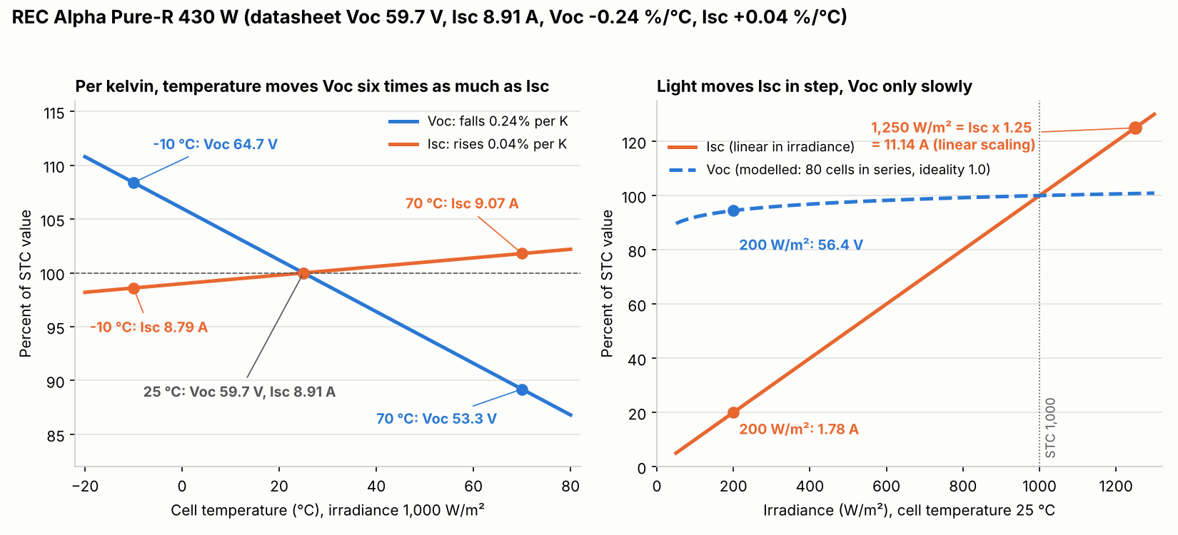
Figure 1. Temperature moves Voc about six times as much as Isc per kelvin, while light moves Isc in step and Voc only slowly.
PVEducation says Voc decreases with temperature because the cell’s saturation current rises rapidly as it warms. So a cold cell gives a higher Voc. Its figure for silicon is about 2.2 mV/°C, with Isc up about 0.06% per °C.
Our datasheet gives −0.24 %/°C for Voc, which is 143 mV per kelvin for the module. If all 80 cells are in series, that is 1.79 mV per cell. That is a little shallower than PVEducation’s silicon figure. The sheet’s Isc coefficient is +0.04 %/°C.
The temperatures here are cell temperatures. The sheet’s NMOT is 44 ± 2 °C at 800 W/m², 20 °C ambient and 1 m/s wind. See ambient and cell temperature and temperature coefficient.
PVEducation says Isc depends linearly on light intensity and Voc logarithmically. The light table in the worked example shows both.
The electrical tables print no rear-side gain, though the sheet names bifacial cells. For bifacial modules, ask the maker how rear gain affects Isc. See bifacial modelling.
How do you calculate cold Voc and Isc x 1.25?
Correct Voc to the lowest expected cell temperature. Multiply by the modules in series and compare with the lowest limit. For current, multiply the datasheet Isc by 1.25.
- From the datasheet for your exact variant and watt class, read STC Voc, STC Isc, the Voc coefficient and the module’s maximum system voltage.
- Take the design low from your AHJ or the NEC 690 page. For the usual design-low convention, cold cells sit at ambient, so use that temperature.
- Cold Voc = Voc at STC × (1 + β × (T − 25)). With β = −0.24%/°C and T = −10 °C, the factor is 1 + 0.0024 × 35 = 1.084.
- Maximum modules = limit ÷ cold Voc, rounded down. Use the lowest of the code, inverter and module limits.
- Current = STC Isc × 1.25. This is the datasheet rating, not a temperature-corrected value. Wire sizing is on the NEC 690 page.
- Sign check: cold Voc must come out above the STC value, and hot Voc below it.
Worked example: REC Alpha Pure-R 430 W at -10, 25 and 70 °C
This 430 W module, from REC’s own site, has a cold Voc of 64.71 V at -10 °C.
Variant: this page uses REC’s US print (footer "UL EN 6.2025", revision /D) for the 430 W class. A second print (the www.recgroup.com file, footer "IEC EN 5.2025") shows the same values. Neither print labels a market beyond the UL or IEC code in its footer.
| Datasheet item (430 W class) | Value |
|---|---|
| Voc, Isc at STC | 59.7 V, 8.91 A |
| Vmpp, Impp at STC | 50.5 V, 8.52 A |
| Coefficients (linear) | Voc −0.24 %/°C, Isc +0.04 %/°C, Pmax −0.24 %/°C |
| NMOT values (see note below) | Voc 56.3 V, Isc 7.20 A (800 W/m², 20 °C ambient) |
| Maximum system voltage | 1,000 V |
| Tolerance | Pmax, Voc and Isc ±3% within one watt class |
The sheet has no 430 W NMOT row. We matched its 327 W row to the 430 W class by column position, and the sheet does not label that block. Treat the NMOT figures as a rough check only.
Our assumptions: all 80 half-cut cells in series (the sheet does not print the layout) and a diode ideality factor of 1.0. That is the ideal-diode value, and it sets how steeply Voc falls with light. The -10 °C case is illustrative, not a design low.
| Cell temperature | Voc factor | Voc per module | Isc per module at 1,000 W/m² |
|---|---|---|---|
| -10 °C | 1.084 (+8.4%) | 64.71 V | 8.79 A (−1.4%) |
| 25 °C | 1.000 | 59.70 V | 8.91 A |
| 70 °C | 0.892 (−10.8%) | 53.25 V | 9.07 A (+1.8%) |
Voc swings 11.46 V across this range and Isc only 0.29 A. Now Isc and Voc against light at 25 °C.
| Irradiance | Isc | Isc as % of STC | Voc (modelled) | Voc as % of STC |
|---|---|---|---|---|
| 200 W/m² | 1.78 A | 20% | 56.39 V | 94.5% |
| 400 W/m² | 3.56 A | 40% | 57.82 V | 96.8% |
| 800 W/m² | 7.13 A | 80% | 59.24 V | 99.2% |
| 1,000 W/m² | 8.91 A | 100% | 59.70 V | 100% |
| 1,250 W/m² | 11.14 A | 125% | 60.16 V | 100.8% |
Model check: our model (80 cells in series and ideality factor 1.0, both assumed) takes 5.5% off Voc at 200 W/m². It takes 0.8% at 800 W/m². The NMOT column that lines up with the 430 W class agrees with it. At a 44 °C cell the model’s Isc is 0.25% below the sheet, and its Voc is 0.34% above. A 2 °C change in that cell temperature moves modelled Voc by 0.29 V. So this is a consistency check, not proof. At 200 W/m² with ideality 1.3, modelled Voc is 7.2% below STC, not 5.5%.
Now the string limit at -10 °C under two ceilings. The real voltage is what the string reaches on that cold day.
| Method | Voc used | Modules at 600 V (real cold voltage) | Modules at 1,000 V (real cold voltage) |
|---|---|---|---|
| Cold Voc (correct) | 64.71 V | 9 (582.4 V) | 15 (970.7 V) |
| STC Voc (common mistake) | 59.70 V | 10 (647.1 V: fails) | 16 (1,035.4 V: fails) |
| Coefficient sign flipped | 54.69 V | 10 (647.1 V: fails) | 18 (1,164.9 V: fails) |
The 600 V ceiling is an example. The 1,000 V figure is this module’s printed maximum system voltage. Allow for tolerance: at +3% on cold Voc, 9 modules reach 599.9 V, only 0.1 V under 600 V. Isc x 1.25 is 11.14 A. Hot Isc is 9.07 A, so temperature changes current far less than the 25% factor does.
Voc and Isc calculator
Enter your datasheet values, a cell temperature and a string length. The defaults reproduce the -10 °C row above. It warns when the Voc coefficient is not negative.
How solar software handles Voc and Isc
Of the five tools below, two document a Voc check and none documents an Isc check.
| Software | Documents a Voc or Isc check? | Method |
|---|---|---|
| OpenSolar | Yes (Voc) | Modelled, site temperatures you enter |
| KACO String Sizing Tool | Yes (Voc) | Checks the string you enter |
| HelioScope | Partly | Modelled, ASHRAE temperatures |
| Enphase compatibility calculator | Partly | Low and high temperatures you enter |
| Fluke TruTest Solar | Not stated | I-V curve analysis |
Not stated: the company page we cite does not say. Partly: the page covers temperature or voltage limits but names neither Voc nor Isc. The notes below give the page wording for each tool.
- OpenSolar: "Voltage limit warnings (for Voc and Vmp)". Warns when they are out of range "due to stringing or temperature effects". No current warning on the page. Support, updated 24 July 2025.
- KACO String Sizing Tool: Shows "max. open circuit voltage of PV generator" and checks system voltage, labelled "open circuit voltage STC", against the module’s maximum. Lists a "Module Temperature" input. The label suggests an STC value, not a cold one. Current check is generator current at MPP. KACO inverters only.
- HelioScope: Stringing considers "the effect of temperature on voltage for the modules". The page names neither Voc nor Isc. Help centre, updated 9 July 2025.
- Enphase compatibility calculator: States a module should not exceed the microinverter’s maximum input DC voltage. The page names neither Voc nor Isc. Support page, checked October 2026.
- Fluke TruTest Solar: The page describes I-V curve analysis and importing panel data from a database. It does not mention Voc, Isc or conversion to STC.
These ratings answer a narrow question: does the page name a Voc or Isc check? Our string sizing and MPPT pages rate some of the same tools on other questions. Tools that check string voltage are ranked in our list of the best solar design software. Free options are in our list of the best free solar calculators for installers.
Common mistakes with Voc and Isc
FAQs
How many modules fit in a string?
Nine, not ten, at a 600 V ceiling and -10 °C in our example. Cold Voc is 64.71 V per module, so 9 modules reach 582.4 V and 10 would reach 647.1 V. Always use the lowest of the code, inverter and module limits.
What is the difference between Voc and Vmp?
Voc is the voltage with no current. Vmp is the voltage at the maximum power point, where the module delivers its rated power. On our datasheet Vmp is 50.5 V against a Voc of 59.7 V, or 84.6%. See Vmp and Imp.
Why does Voc go up when it is cold?
A colder cell has a lower saturation current, so its Voc is higher. PVEducation says the cell’s saturation current rises rapidly with temperature, which makes Voc fall as cells warm. In the example it is 8.4% above STC at -10 °C.
Why is Isc multiplied by 1.25?
The factor covers peak irradiance above the STC value. Wiles says peak irradiance may approach 1,250 W/m² under clear skies. For this module, 1.25 x Isc equals its current at 1,250 W/m² if current scales linearly. A second 125% for continuous current may apply to wire and devices, as the NEC 690 page explains.
Does Isc change with temperature?
Slightly. On our datasheet it rises 0.04% per kelvin. So it is 1.4% lower at -10 °C and 1.8% higher at 70 °C. Irradiance matters far more: Isc falls to 20% at 200 W/m².
Will a field reading match the datasheet Voc?
Not unless conditions match STC. A reading depends on cell temperature and irradiance at the time. The commissioning report page shows how to compute the expected value.
Related terms
- Vmp and Imp: the voltage and current at the maximum power point.
- Temperature coefficient: how much a module value changes per kelvin.
- Cold temperature voltage correction: scaling Voc up to the design low.
Next step: correct your own module’s Voc to the design low and count the modules. Then compare tools in the best solar design software list, or use the best free solar calculators for installers.
Sources
- REC Alpha Pure-R datasheet, US print (UL EN 6.2025) and IEC print (IEC EN 5.2025) (checked October 2026).
- PVEducation: open-circuit voltage, short-circuit current, effect of temperature and effect of light intensity (checked October 2026).
- John Wiles, IAEI Magazine, posted 5 January 2018 (November/December 2017 issue, 2017 NEC) and Mike Holt, EC&M, July 2024 (edition not named) (checked October 2026).
- Company pages: OpenSolar, KACO, HelioScope, Enphase and Fluke (checked October 2026).
- Search gap check: Sinovoltaics and Solar4RVs (checked October 2026).
Last updated 30 October 2026. Next scheduled review: 30 January 2027.