Key takeaways
- Vmp × Imp is Pmax. On the REC 430 W class sheet, 50.5 V × 8.52 A is 430.26 W against 430 W printed. The fill factor is 0.808.
- This sheet prints no Vmp coefficient. Our band of -0.24 to -0.28 %/°C is an estimate, not a datasheet value. Ask the maker, and use -0.28 as the cautious end.
- Hot Vmp sets the short end of a string. With an invented 35 °C ambient and 200 V MPPT floor, 4 modules give 202.0 V at STC but 179.4 V at 65 °C.
- The coefficient matters only near the floor. With an example 225 V floor, 5 modules pass at -0.24 (228.3 V) and fail at -0.28 (224.2 V).
- Imp sets input current. Two strings draw 17.04 A on an example 20 A input. They draw 21.3 A at 1,250 W/m² (25 °C) if Imp scales with light.
Run the hot-day string Vmp calculator, or see the best solar design software for tools that warn on string voltage.
Vmp and Imp at a glance
Vmp and Imp are the two coordinates of the peak of a module’s power curve. Hot Vmp decides how short a string can be before summer drags it under the inverter’s floor. Imp sets input current. The cold side is on the Voc and Isc page and the string sizing page.
| Item | Detail |
|---|---|
| Formula | Pmax = Vmp × Imp. Fill factor = (Vmp × Imp) ÷ (Voc × Isc). String Vmp at cell temperature T = modules × Vmp × (1 + β × (T − 25)), with β negative. |
| Unit / typical range | Volts and amps. Example: 50.5 V and 8.52 A (REC 430 W class). No typical range stated. |
| Where it matters | The hot-day MPPT minimum check, current per inverter input, library entries and field I-V readings. |
| Standard or rule | The sheet defines STC as air mass 1.5, 1,000 W/m² and 25 °C. See standard test conditions. |
| In software | Some tools warn when string Vmp leaves the inverter’s window at site temperature extremes. |
Why do Vmp and Imp matter, and how do they relate to Pmax, Voc and fill factor?
Vmp and Imp are where the power curve peaks. Multiply them for Pmax. Divide Pmax by Voc × Isc for the fill factor, which says how square the I-V curve is.
PVEducation says "VMP is when the derivative of the power with respect to V is zero". It defines fill factor as the maximum power divided by Isc times Voc. TU Delft (modified 9 March 2016) gives the cell form, FF = (Jmp × Vmp) ÷ (Jsc × Voc).
The REC sheet prints STC as "air mass AM 1.5, irradiance 1000 W/m², temperature 25°C". Its ±3% tolerance note names Pmax, Voc and Isc, not Vmp or Imp.
| Quantity (REC 430 W class) | Value | How it is made |
|---|---|---|
| Vmp × Imp | 430.26 W | 50.5 × 8.52. It is 0.06% above the printed 430 W, from rounding. |
| Fill factor | 0.808 | 430 ÷ (59.7 × 8.91). From Vmp × Imp it is 0.809. |
| Vmp ÷ Voc | 0.846 | 50.5 ÷ 59.7. On this sheet Vmp is 84.6% of Voc and Imp 95.6% of Isc. |
| Imp ÷ Isc | 0.956 | 8.52 ÷ 8.91 |
Fill factor also falls with heat, by about 0.04 %/°C. Its coefficient is the Pmax coefficient (-0.24), minus the Voc coefficient (-0.24), minus the Isc coefficient (+0.04). That sums to -0.04. The fill factor reaches 0.796 at 65 °C. See fill factor and I-V curve tracing.
How do Vmp and Imp change with temperature?
For this heterojunction module, Vmp falls by roughly 0.24 to 0.28 % per kelvin as cells heat up (our band, the sheet prints none). Imp rises only slightly. Other modules can be steeper. Our MPPT page fits -0.30 for a different module, and our string sizing page estimates -0.34 for another.
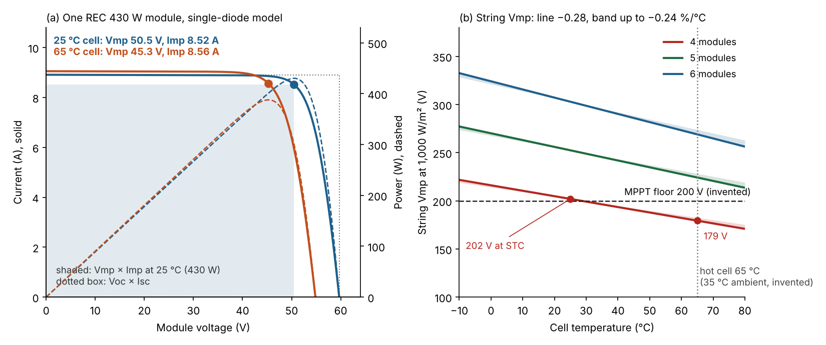
Figure 1. At a 65 °C cell, a 4-module string falls from 202.0 V to 179.4 V, 20.6 V under an example 200 V floor, while the module’s current barely moves.
Because Pmax = Vmp × Imp, the relative coefficients add: Pmax coefficient = Vmp coefficient + Imp coefficient, to first order. The sheet prints Pmax (-0.24 %/°C) and Isc (+0.04 %/°C), but no Vmp or Imp coefficient. We assume Imp’s coefficient lies between 0 and Isc’s (+0.04). The sheet does not say so. Then Vmp’s lies between -0.24 and -0.28, and that band is our estimate. The steeper end is the cautious one for a minimum-voltage check.
How the band was checked
- Single-diode fit: a simple cell model fitted to the five datasheet points (Figure 1a). It used 80 cells in series, 2,000 ohm shunt resistance and a 1.12 eV band gap. It gave Imp +0.013 and Vmp -0.258 %/°C, with Pmax -0.246. The fit’s Voc coefficient is -0.20 against -0.24 printed.
- Nine variants of the fit: two matched the printed Pmax coefficient within 0.03 and gave Vmp from -0.23 to -0.26. Fits that match Voc overshoot Pmax and give Vmp near -0.30.
- How to read it: the fit checks Imp’s small positive coefficient. It is not a measurement. The -0.28 end rests on Imp’s coefficient not exceeding Isc’s, and printed values are rounded.
Do not reuse the Voc coefficient
- Valentin Software staff replied on their forum on 28 January 2019. They call mixing up the open-circuit and MPP voltage coefficients "a common mistake, even among experts in the community". They add: "These are not the same!"
- On 1 February 2019 the same staff member guessed that the Pmax coefficient is closer to the Vmp one than Voc’s is. He said to use it if you cannot simulate. That points to -0.24, but we use the steeper -0.28 for the floor check because it is the safer assumption.
Sandia’s PV Array Performance Model (PVPMC, metadata updated 2 January 2026) gives Vmp its own term, β_Vmp × (Tc − 25 °C). The sheet’s NMOT block has four columns that are not labelled by power class. We assume the last one is the 430 W class, and it fits. Vmp of 47.6 V is 5.7% under STC at 44 °C, 800 W/m². The 19 K rise explains 4.6% to 5.3% at -0.24 to -0.28, and light about 1.0% on our ideality 1.0 assumption. NMOT is 44 ± 2 °C, so this is a check only. See temperature coefficient and NOCT and NMOT.
How do you check a string against the MPPT minimum?
Find the hot cell temperature and correct Vmp to it. Multiply by the modules in the string and compare with the inverter’s minimum. Then check current.
- Read Vmp, Imp, Pmax, the coefficients and NMOT for your exact variant. Check Vmp × Imp is within 0.5% of Pmax (our allowance).
- Take the Vmp coefficient from the maker, a PAN or Sandia entry, or a band. Use the steeper end.
- Cell temperature = design high ambient + (NMOT − 20) × irradiance ÷ 800, as on the string sizing page. See ambient and cell temperature.
- Hot Vmp = Vmp × (1 + β × (T − 25)). String voltage = modules × hot Vmp.
- Fewest modules = floor ÷ hot Vmp, rounded up. The start-up check on hot Voc is on the string sizing page.
- Current per input = Imp × parallel strings, against the operating rating.
Worked example: REC 430 W class on an example inverter
Four modules clear a 200 V floor at STC by 2.0 V. At a 65 °C cell they miss it by 20.6 V. Five pass at every coefficient tried.
Module values come from REC’s US print, 430 W class, as on the Voc and Isc page. The footer reads "UL EN 6.2025", revision /D. The floors, the 20 A limit and the 35 °C ambient are example, not product or site data. Cell rise is (44 − 20) × 1,000 ÷ 800 = 30 K, so the cell is at 65 °C. At -0.28 %/°C, hot Vmp is 44.84 V per module.
| Modules | String Vmp at STC | Against 200 V floor | String Vmp at 65 °C | Against 200 V floor |
|---|---|---|---|---|
| 4 | 202.0 V | 2.0 V over | 179.4 V | 20.6 V under: fails |
| 5 | 252.5 V | 52.5 V over | 224.2 V | 24.2 V over: passes |
| 6 | 303.0 V | 103.0 V over | 269.1 V | 69.1 V over: passes |
The fewest modules is 4 by STC Vmp but 5 by hot Vmp. Four modules clear the floor only while the cell is under 28.5 °C, which is ambient below -1.5 °C at 1,000 W/m². At -0.24, -0.28 and -0.32 the answer is 5 every time.
The coefficient matters when the margin is thin. Now use an example 225 V floor and 5 modules.
| Vmp coefficient used | 5 modules at 65 °C | Against 225 V floor |
|---|---|---|
| -0.24 %/°C (Voc and Pmax coefficient) | 228.3 V | 3.3 V over: passes |
| -0.258 %/°C (our single-diode fit) | 226.5 V | 1.5 V over: passes |
| -0.28 %/°C (Pmax minus Isc) | 224.2 V | 0.8 V under: fails |
The pass or fail result changes inside the band, so the coefficient decides it. Use the steeper end unless the maker prints a Vmp coefficient.
One string draws Imp, 8.52 A. Two draw 17.04 A on the example 20 A input, and three draw 25.56 A. If Imp scales with light like Isc (our fit assumes so), two strings draw 21.3 A at 1,250 W/m² and 25 °C.
Vmp and Imp calculator
Enter your datasheet values, a hot ambient, a string length and the inverter’s minimum. The defaults reproduce the 4-module row. It warns on a non-negative Vmp coefficient or a Vmp × Imp gap. To compare more free tools, see the best free solar calculators for installers.
Datasheet or tool library: which Vmp and Imp should you trust?
Trust the maker’s current datasheet. A library entry is a copy. Check its Vmp, Imp and coefficient like any other field.
The equipment datasheets page shows one module whose printed Vmp and Imp changed between revisions. KACO’s tool page tells users to verify the database module against the datasheet. A library may hold a Vmp coefficient the sheet never printed, so ask where it came from. The pvlib 0.16.1 docs list Bvmpo among Sandia parameters and say the CEC module database lacks them.
How solar software handles Vmp and Imp
Of the four tools below, two design tools document a Vmp limit check, and one of them adds a current check. pvlib computes both values.
| Software | Documents a Vmp or Imp check? | Method |
|---|---|---|
| OpenSolar | Yes (Vmp) | Modelled, site temperatures you enter |
| KACO String Sizing Tool | Yes (MPP voltage and current) | Checks the string you enter |
| HelioScope | Partly | Modelled, ASHRAE temperatures |
| pvlib python | Yes | Library you code against |
- OpenSolar: Lists "Voltage limit warnings (for Voc and Vmp)", with "Vmp at high temperatures" in hover text. There is no current check on the page. Support, updated 24 July 2025.
- KACO String Sizing Tool: Compares "min. MPP voltage of inverter" with "min MPP voltage of PV generator", and "Generator current in MPP" with the inverter’s maximum input current. Tool page labels, undated, checked October 2026. No method described.
- HelioScope: Stringing help says recommendations "will not exceed the MPP range of your inverter in both hot and cold conditions". A second page calls power lost outside the range voltage clipping. Neither page names Vmp or Imp. Updated 9 and 8 July 2025.
- pvlib python: sapm and singlediode return v_mp, i_mp and p_mp. It computes the values only, with no inverter window check. Docs 0.16.1, October 2026.
These ratings ask whether the page names a Vmp or Imp check. Partly: the page describes a range check but does not name Vmp or Imp. Design tools that flag string voltage limits are ranked in our list of the best solar design software.
Common mistakes with Vmp and Imp
FAQs
Is Vmp the maximum voltage a panel can give?
No. Voc is the highest voltage, with no current flowing. Vmp is the voltage at the peak of the power curve. On the example sheet Vmp is 84.6% of Voc. See Voc and Isc.
Is string Vmp the same as the inverter’s MPPT voltage?
No. String Vmp is modules × Vmp at the current cell temperature. The MPPT range is the inverter’s window, and the tracker follows the peak while string Vmp stays inside it. Power optimisers change the string rules.
Where do I find the Vmp temperature coefficient?
Start with the maker’s datasheet, but many sheets do not print it. The REC sheet prints Pmax, Voc and Isc coefficients only. Ask the maker, find a PAN or Sandia entry, or build a band as above.
Does Imp change with temperature?
Only slightly. Imp rises a little as cells heat up. Vmp falls by roughly 0.24 to 0.28 % per kelvin on the example module (our band, the sheet prints none). Imp sets input current, so the check that matters is against the inverter input rating.
How do I check string Vmp against the MPPT minimum?
Correct Vmp to the hot cell temperature, multiply by the modules in the string and compare the result with the inverter’s minimum. Use the steeper coefficient estimate if the sheet prints none. The worked example shows the steps with an example floor.
Related terms
- Voc and Isc: the open-circuit voltage and short-circuit current of a module.
- Temperature coefficient: how much a module value changes per kelvin.
- Cold temperature voltage correction: scaling Voc up to the design low.
Next step: to run the hot-day check in a tool, compare the best solar design software, or use the best free solar calculators for installers.
Sources
- REC Alpha Pure-R datasheet, US print (UL EN 6.2025) (checked 30 October 2026).
- PVEducation, fill factor (no date on the page) (checked October 2026).
- TU Delft OpenCourseWare, Solar Cell Performance (modified 9 March 2016) (checked October 2026).
- Sandia PVPMC, PV Array Performance Model (metadata updated 2 January 2026) and pvlib sapm (0.16.1) (checked October 2026).
- Valentin Software forum, "Calculation of min MPP voltage" (staff replies 28 January and 1 February 2019) (checked October 2026).
- Company pages (checked October 2026): OpenSolar, KACO, HelioScope stringing and HelioScope inverter modelling.
Last updated 30 October 2026. Next scheduled review: 30 January 2027.