Key takeaways
- This example’s block has 1,320 strings (15.2 MWdc). Trenches every 6 rows instead of every 2 cut trench from 8,556 m to 3,012 m (65% less).
- String cable grew 3.1% on unrounded values, from about 213.7 km to about 220.5 km.
- The sparser layout is cheaper once a metre of trench costs more than 2.55 conductor-metres of cable. That break-even is for this example’s block and assumes equal price per conductor-metre.
- Straight lines from each string to the centre are 23.5% shorter than layout A’s cable but cannot be built. Right-angle runs with no trench rules are 1.9% shorter.
- The longest run is 315 m in both layouts. At 6 mm² copper and 70°C it drops 2.27% of string voltage (example 11 A, 1,050 V).
To route and quantify cable runs in software, see the best utility-scale solar design software.
Cable routing and trenching at a glance
Routing fixes how long each cable is. Trenching fixes how much ground is dug to hold the cables.
| Item | Detail |
|---|---|
| Formula | Conductor resistance R = ρ × L ÷ A. Drop = current × loop resistance ÷ voltage. Loop length is 2 × one-way length |
| Unit and range | Metres of trench and conductor-metres. No typical range is given here, because it depends on layout, block size and string voltage |
| Where it matters | Layout design, quantity take-off, EPC pricing, voltage-drop checks, civil works planning |
| Standard or rule | No single standard. Trench depth, cable spacing and current rating come from the adopted electrical code and the cable maker. This page gives none of those values |
| In software | Some layout tools generate routes along trench lines. Only PVcase documents DC runs feeding its Bill of Materials. See the table below |
Why cable routing and trenching matter for installers
Routing sets two bills at once: cable and civil work. They pull in opposite directions, so the cheapest layout is not always the one with the shortest cable.
A tight trench network keeps stubs short but means a lot of digging. A sparse network cuts excavation and lengthens the stubs. Figure 1 shows how lopsided that swap can be.
Cables in one trench also interact. PVcase’s release notes say cable spacing in the trench affects both trench dimensions and cable sizing.
The quantity take-off then carries the result into the estimate. See bill of quantities. Site limits such as wetlands or easements come from GIS layers and become keep-out zones for the routes.
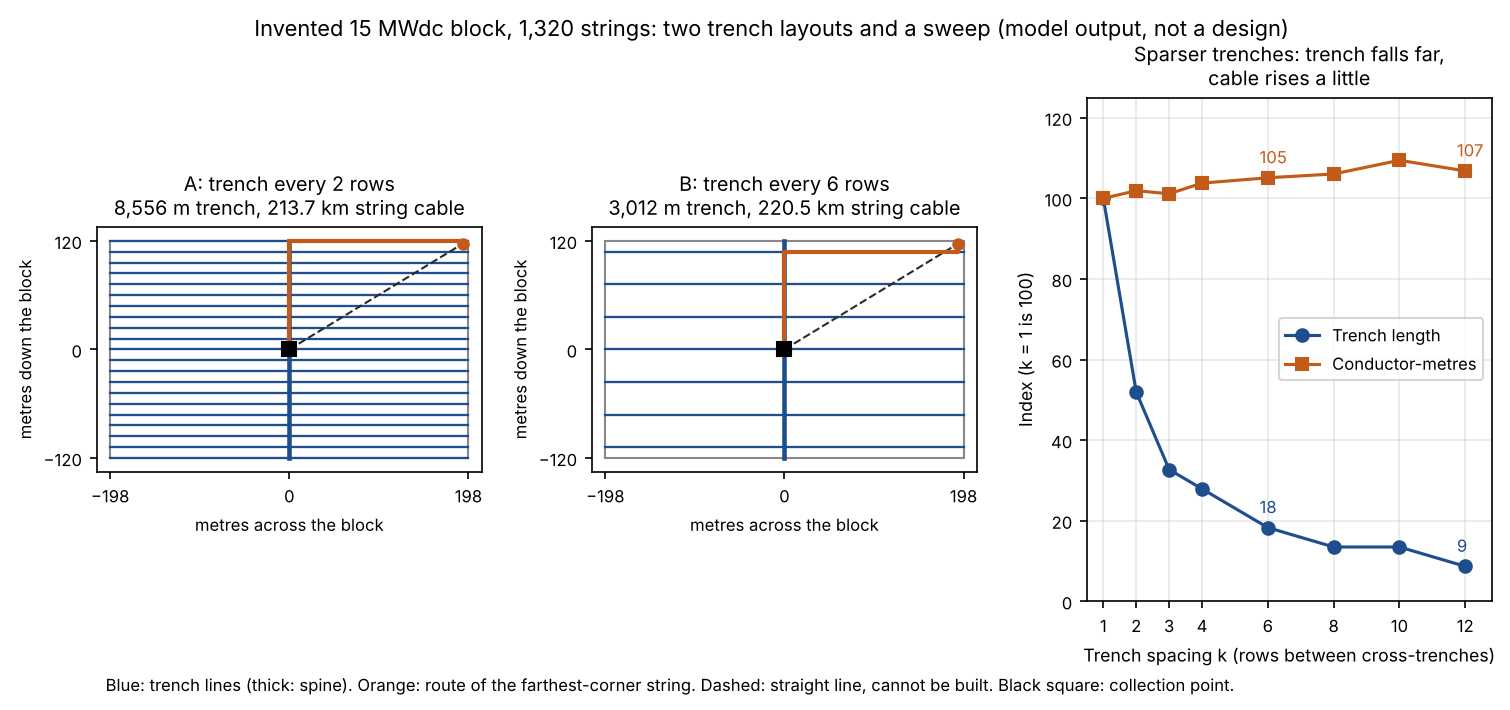
Figure 1. In this example’s block, trenches every 6 rows instead of every 2 cut trench length by 65% and added 3.1% to string cable.
How are cable routes chosen: shortest path or trench network?
The two tools that document trench routing, PVcase and PVFARM, use a trench network, not free straight lines. Shortest path inside that network is the basic idea, and constraints bend it.
- PVcase Ground Mount, what you draw. You draw trench lines as AutoCAD polylines inside the PV area. Its help says it is crucial that they touch or overlap.
- PVcase Ground Mount, what it routes. A setting called cable stickiness picks the behaviour. Shortest path finds the shortest route possible, which may not match expectations. Stick keeps routes inside the trenches you defined. Auto generation lays cables for all strings and devices. Semi-auto lets you pick individual ones.
- PVFARM, what you set. Its medium-voltage routing section lets you set excluded boundaries that circuits cannot cross. You can add waypoints to steer nearby circuits.
- PVFARM, what it trades off. A bias setting adjusts the algorithm’s preference between less wire and less trench. There is also an above-ground option for MV conductors.
- Trench sharing means several circuits share one trench. It saves digging but packs cables together. PVcase’s cable separation settings cover the number of layers, the distance from the trench sides and the vertical and horizontal spacing between cables. PVFARM’s trench page gives separate width and depth formulas for DC feeder, AC feeder, MV, whip, and whip-and-feeder trenches. Width grows with the number of cables, their spacing and their diameter.
- The maths. A paper from the Karlsruhe Institute of Technology (arXiv 2410.15031) frames solar-farm cabling as a tree, with strings as leaves and one point as the root. Its introduction says a solver (Gurobi) struggled on several larger instances to find even a feasible layout. It does not discuss trenches. An INFORMS Journal on Computing article models the problem as a generalised capacitated minimum spanning tree that minimises cable installation cost.
How do you calculate cable length, voltage drop and quantity?
Add up each string’s route, convert length to resistance, then to drop. The same route lengths give the quantity. Five steps cover it.
- Find each string’s one-way length L: the stub to its trench plus the run along the trench to the collection point.
- Take resistance from R = ρ × L ÷ A (Engineering ToolBox). Use ρ in ohm metres, L in metres and A in square metres. A string needs 2 × L, because the current goes out and back.
- Correct ρ for temperature: R = R0 × [1 + α × (T2 − T1)] (mycableengineering). Engineering ToolBox lists copper at 1.724e-8 ohm metre and α = 0.00393 per °C at 20°C. At 70°C that is 20.6 ohm mm² per km. The voltage-drop page uses 1.68e-8 from HyperPhysics. The 2.6% gap does not change the comparison between layouts.
- Drop (%) = current × loop resistance ÷ string voltage × 100. For targets and sources, see voltage drop calculation.
- Quantity: conductor-metres = 2 × the sum of all L, plus slack. Trench metres are the sum of the trench lines.
Cross-check the resistivity your tool uses
PVcase’s help lists 23.7 ohm mm² per km for copper and 37.6 for aluminium, and states no temperature. The copper figure is about 15% above our 70°C value.
Check the vertical drop too. HelioScope’s help says it does not account for the vertical height of field segments when calculating wire lengths (posted 4 March 2026). On sloped ground, add that height yourself or use a 3D tool. PVcase can convert cables to 3D so the trench follows the terrain. See topography and terrain modelling.
Worked example: two trench layouts for one block
Same block, same strings, two trench spacings. Layout B digs 65% less trench and uses 3.1% more string cable. All inputs are example.
| Input (example) | Value |
|---|---|
| Block | 33 columns of strings, 12 m apart, by 40 rows at 6 m pitch: 396 m by 240 m |
| Strings and size | 1,320 strings, 11 A and 1,050 V each: 15.2 MWdc |
| Conductor | 6 mm² copper at 70°C for the main run. Target drop 1.5%. 5% slack on quantities |
| Routing rule | Each string goes to its nearest trench line, along it to the spine, then down the spine to the block centre |
| Layout A and B | Cross-trench every 2 rows (21 lines) and every 6 rows (7 lines), plus a spine down the middle |
The table below puts the two layouts side by side.
| Result (modelled) | Layout A | Layout B |
|---|---|---|
| Trench length (m) | 8,556 | 3,012 |
| String cable, one way (km) | 213.7 | 220.5 |
| Mean and longest run (m) | 161.9 and 315 | 167.0 and 315 |
| Conductor-metres with slack | 448,812 | 462,949 |
| Mean drop at 6 mm² | 1.17% | 1.20% |
| Strings over 1.5% at 6 mm² | 324 (24.5%) | 372 (28.2%) |
| Cable loss at full string current | 177.8 kW | 183.4 kW |
Loss is at peak string current, not annual energy. The voltage-drop page explains the difference.
Lower bounds. The straight-line distances from all strings to the block centre total 163,479 m. Right-angle distances with no trench rules total 209,760 m. Layout A is 1.9% longer than the second figure and layout B is 5.1% longer. Neither bound can be built.
Take-off. If each string takes the smallest size that meets 1.5%, conductor-metres with slack split as below. The catalogue (4, 6, 10, 16 and 25 mm²) is example.
| Size | Layout A | Layout B |
|---|---|---|
| 4 mm² | 102,564 | 93,114 |
| 6 mm² | 176,677 | 174,560 |
| 10 mm² | 169,571 | 195,275 |
Layout B saves 5,544 m of trench and adds 14,137 conductor-metres. That is 2.55 conductor-metres per trench metre saved. If a trench metre costs more than 2.55 conductor-metres of cable, B wins. B also needs more 10 mm² cable, which costs more per metre. So the true break-even sits a little higher.
Over trench spacings from 1 to 12 rows, trench length falls from 16,476 m to 1,428 m. Conductor-metres stay within 9.4% of the 1-row figure (example block). They do not rise smoothly: 10 rows needs 482,076 and 12 rows needs 470,434, because of where the last trench line falls.
The model counts string cable only. It leaves out combiners, DC feeders, AC cable, slope and obstacles, and puts every string on one spine. Real blocks add combiners or string inverters, which shorten the long runs.
Cable routing and trenching calculator
Enter your own block, trench spacings, string current and voltage, and conductor. The defaults reproduce the tables above. Prices are optional and blank by default.
How solar software handles cable routing and trenching
PVcase and PVFARM route cables along trench networks. HelioScope routes strings only, and RatedPower does not state whether it routes along a trench network. PVFARM and RatedPower both state trench width and depth values.
| Software | Routes cables along a trench network? | Trench dimensions or quantities? | Source and date |
|---|---|---|---|
| PVcase Ground Mount | Yes | Partly | PVcase help, fixed tilt cabling, updated 3 February 2025. Cabling prerequisites page, no date shown. Release notes 2.29, no date shown |
| PVFARM | Yes, for MV circuits | Yes | PVFARM electrical solutions page, undated (© 2026). Help pages on the electrical panel and on trenches, undated |
| HelioScope | No (string routing only) | Not stated | HelioScope help, electrical design (no date shown). Optimise conductor sizes, updated 9 July 2025. Wire lengths, posted 4 March 2026 |
| RatedPower | Not stated | Yes (width and depth, not a trench quantity) | RatedPower knowledge base, trench depth and width, no date shown (read November 2026) |
Not stated: the company pages we cite do not say. RatedPower’s routing method is still a gap in our reading, not a finding about the tool. Partly: the pages cover part of the job, such as cable spacing that affects trench size without a trench volume.
How and where each tool works:
- PVcase Ground Mount: you draw trench lines. Auto generation follows them, with Shortest path or Stick. AC uses Stick per transformer. Cable separation sets layers and spacing, and affects trench dimensions. DC runs feed the Bill of Materials. The company pages do not state trench volume.
- PVFARM: MV routing has excluded boundaries, waypoints and a wire-versus-trench bias (bias setting). The electrical page says trench width and depth are calculated, with safety spacing, and that earthwork and a trench BoQ are estimated. LV wiring follows the chosen scheme. The company pages do not describe LV routing paths.
- HelioScope: you choose string routing along or up and down the array. Moving inverters and combiners re-routes wires and recalculates distances and STC voltage drop. No trench network is described. Wire lengths ignore the vertical height of field segments.
- RatedPower: its knowledge base states trench widths from 400 mm to 800 mm for low voltage and 800 mm to 1,200 mm for medium voltage. Its CAD layout draws a fixed 400 mm or 600 mm width regardless of the real figure. Depth runs from 500 mm to 3,500 mm in 500 mm steps. The minimum is 1,000 mm, set by 600 mm of cover for low voltage and 700 mm for medium voltage. Its "pvDesign cabling topology" article would not open, so we cannot rate the routing method.
For layout tools that route along trench lines, see the best utility-scale solar design software. For automated layout, see the best AI solar design software.
Common mistakes with cable routing and trenching
FAQs
Is the shortest cable route the cheapest?
No. Cable and trench are separate costs. A sparser trench layout can win once a trench metre costs more than the worked example’s break-even. Layout B has longer cable but less trench.
What is trench sharing?
It means several cable circuits, for example DC and AC, run in one trench. It cuts excavation. Cable spacing in the trench then affects trench size and cable sizing, according to PVcase’s release notes.
Do layout tools draw the trench lines for you?
In PVcase Ground Mount you draw them as polylines, and the cables follow. PVFARM’s MV routing takes waypoints and excluded boundaries from you. The company pages do not say trench lines are drawn automatically.
How does route length change voltage drop?
Drop grows in direct proportion to length at the same size and current. Doubling the run doubles the drop, and doubling the conductor area halves it. See the voltage-drop page for targets.
Related terms
- Voltage drop calculation: the volts a cable loses, from current and resistance.
- Bill of quantities: the priced list of materials and works that routing feeds.
- Utility-scale layout optimisation: how block size and GCR also move cable length.
Next step: ask each tool whether its routes follow trench lines and whether it reports trench length, then compare them in the best utility-scale solar design software. PVcase and PVFARM both route along trenches.
Sources
- Model: the page’s own arithmetic, with all inputs example.
- Engineering ToolBox, resistivity and conductivity: R = ρ L ÷ A. Copper and aluminium at 20°C (checked October 2026).
- mycableengineering, resistance: R = ρ L ÷ A and the temperature correction (checked October 2026).
- PVcase help, fixed tilt cabling (updated 3 February 2025). PVcase help, cabling prerequisites (no date shown). PVcase release notes 2.29, Cable Separation (no date shown). All checked October 2026.
- PVFARM, electrical solutions. PVFARM, the electrical panel. PVFARM, how trenches work. PVFARM, electrical patterns. All undated. Checked October 2026.
- RatedPower knowledge base, What depth and width values are being considered for trenches?, undated. Read November 2026.
- HelioScope help: electrical design, optimise conductor sizes (updated 9 July 2025), wire lengths (posted 4 March 2026). Checked October 2026.
- Bläsius, Göttlicher, Gritzbach and Yi (KIT), The Constrained Layer Tree Problem and Applications to Solar Farm Cabling, arXiv 2410.15031. INFORMS Journal on Computing, A Branch-and-Price-and-Cut Algorithm for the Cable-Routing Problem in Solar Power Plants. Checked October 2026.
Last updated 30 October 2026. Next scheduled review: 30 January 2027.