Key takeaways
- A 100 MW plant at 0.95 power factor needs 105.3 MVA (100 ÷ 0.95). The transformer’s own 12.0 Mvar at 10% impedance lifts the load on a 100 MVA unit to 109.5 MVA.
- A larger unit uses less reactive power, so the smallest rating that is not overloaded is 109.1 MVA at 10% impedance and 113.2 MVA at 18%. Unity gives 100.5.
- At 0.95, a 100 MVA datasheet unit loses 934 MWh a year, 0.47% of 197,851 MWh in a pvlib typical year. The loss data are a scale example only.
- At an assumed 1.5 times rated, inverters give 2.75 kA, 18.7% of the sum with a placeholder 2,500 MVA grid. The share runs 13.3% to 23.5% at 1.0 to 2.0 times.
- The utility study, not the designer, decides who builds the grid-side equipment.
To lay out and size a plant substation in software, see the best utility-scale solar design software.
Substation design at a glance
Substation design sets the transformer, switchgear, protection and grounding between the feeders and the utility line. The utility then checks the result in its study.
| Item | Detail |
|---|---|
| Formula | S = √(P² + Q²). At 0.95 and 100 MW, P ÷ 0.95 = 105.3 MVA before the transformer’s own use. |
| Reactive burden and loss | Q at the MV side = Q at the high side + X × S² ÷ rating. Load loss follows S². No-load loss does not change with load. |
| Unit / typical range | MVA for the transformer, kW for loss. No neutral benchmark is given. The assumed 100 MW case needs 109.1 to 113.2 MVA, depending on impedance. |
| Where it matters | Interconnection agreement, transformer order, loss budget and the single-line diagram. |
| Standard or rule | Not the standard text. FERC Order 827 (16 June 2016) requires dynamic reactive power within 0.95 leading to 0.95 lagging. It applies at the high side of the generator substation, for newly interconnecting non-synchronous generators without a signed Facilities Study Agreement at the effective date. A transmission provider may set a different power factor range for all such generators. |
| In software | Layout and electrical tools draw the substation. Analysis tools model grounding and loss (see the table below). |
Why does substation design matter for utility-scale solar?
The substation is where the plant meets the utility’s rules. A transformer sized for real power alone can fail the reactive test.
Losses also carry a price. One Brookside Solar transformer sheet (undated) prints 8,000 per kW of no-load loss. It prints 2,600 per kW of load loss. The price is read as USD. The supplier fills in the loss values.
To see the process, read the interconnection application and queue pages.
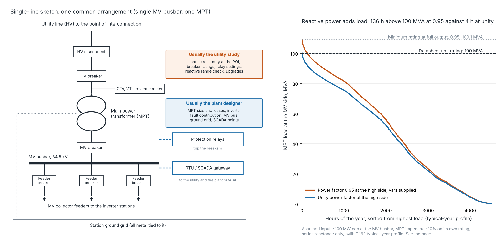
Figure 1. At 0.95 power factor the assumed 100 MW plant loads a 100 MVA transformer above its rating for 136 hours, against 4 at unity. The unit has 10% impedance, and the loss data are a scale example from a 50 Hz three-winding datasheet (pvlib typical year).
What is inside a solar plant substation?
RatedPower’s glossary page (updated 5 May 2025) lists seven parts. These are transformers, breakers, switchgear, busbars, instrument transformers, protection and control, and communications. It says solar substations have no standard layout.
It names three layouts: line-to-transformer, single busbar and double busbar. Figure 1 shows a single busbar. The examples below come from three project documents.
- Main power transformer (MPT): the Somerset Solar sheet (Appendix 5-D, Revision R002, 125 MW) calls for 84/112/140 MVA. Voltage is 345 kV to 34.5 kV. It also asks for a delta tertiary and 33 tap steps of 0.625%.
- Breakers and disconnects: PJM’s AG1-105 study (December 2024, 90 MW solar) describes a three-breaker 115 kV ring. The transmission owner builds it. The developer also supplies breakers up to the point where ownership changes. The study lists breakers in both scopes and does not settle the overlap.
- Protection: SPP’s GEN-2023-153 study (Rev. 0, 30 January 2026, file labelled Draft, 120 MW) describes primary and secondary relays on the 115 kV tie line. The customer supplies them.
- Metering: in AG1-105 the developer supplies metering of net MW and Mvar. The owner installs revenue metering on its side. GEN-2023-153 asks for metering of generation and parasitic load.
- SCADA: GEN-2023-153 asks for an RTU that suits DNP3, linked by 48-strand single-mode fibre. See SCADA.
- Grounding: AG1-105 says the two stations’ grounding systems will be tied together. The developer prepares the site 10 feet beyond the fence for this.
The single-line diagram is the drawing that shows all of this. MV/LV design covers the feeders that reach the busbar.
What does the designer calculate?
The designer works out five things before the utility’s study: transformer size, loss, fault contribution, reactive capability and the ground grid.
- Transformer rating: find real and reactive power at the MV side. Take the apparent power, then add any margin the maker allows. See power factor and reactive power for the kVA limit.
- Losses: take no-load and load loss from the maker’s guaranteed values. Apply them to the plant’s hourly output. See 8760 hourly simulation.
- Inverter fault contribution: multiply rated current by a multiple. NREL’s 2010 report on inverter-based resources gives a rule of thumb. It is 1 to 2 times full-load current for one cycle or less. It cites an EPRI 1990 maximum of 150%. Its own figures vary. It shows 2 to 5 times in tests, 2-4 times in its conclusions and 150% from EPRI. It tested very few units.
- Reactive capability: show that inverters and any capacitors meet the range at the high side. Count the losses in the transformer and collector.
- Ground grid: ETAP’s page describes automatic generation of a two-layer soil model and a Wenner four-pin method. It names EN 50522, IEEE 80 and IEEE 81. No limits are quoted.
Worked example: a 100 MWac plant, one transformer
This example sizes a transformer for 100 MW at the MV busbar. It then runs losses and fault current.
- Plant: 100 MW cap at the 34.5 kV busbar (assumed). 130 MWdc, DC/AC 1.30, single-axis tracker with backtracking, ground cover ratio 0.35, pvlib 0.16.1 PVWatts-style model with 14% losses (assumed).
- Weather: pvlib’s bundled TMY3 file 723170TYA, Greensboro Piedmont Triad Intl, NC. A typical year, not measured. Capacity factor 22.6% (197,851 MWh at the MV busbar).
- Power factor: 0.95 at the high side, held at full output and in every hour of Step 2, vars supplied or absorbed. This is the Order 827 range, used as an assumption.
- Transformer: Impedance 10% on its own rating (the Somerset sheet specifies 10%, we assume it). Series reactance only, voltage 1.0 per unit, no magnetising current.
- Losses: Datasheet titled ‘station transformer 100 mva 230kv-datasheet revb’: 50 kW no-load and 330 kW copper (load) loss, under ‘guaranteed losses at nominal ratio’. Fan loss (8 kW) is excluded.
The loss datasheet is an undated uploaded copy with no named maker. It describes a 100/60/60 MVA, 50 Hz, three-winding 230 kV unit with impedance of at least 18%. The model applies its losses to a 10% two-winding unit, so they are a scale example only.
Step 1, size. The transformer’s own reactance uses 12.0 Mvar at full load. The inverters must supply that on top of the 0.95 requirement at the high side. Power factor alone needs 105.3 MVA. The transformer’s burden lifts it to 109.5. The trial ratings are ours, and impedance is 10% on each.
| Case at the high side (10% impedance) | 100 MVA unit | 112 MVA unit | 125 MVA unit | Minimum rating |
|---|---|---|---|---|
| Unity power factor | 100.5 (100.5%) | 100.4 (89.6%) | 100.3 (80.3%) | 100.5 |
| 0.95, vars supplied | 109.5 (109.5%) | 109.0 (97.3%) | 108.5 (86.8%) | 109.1 |
| 0.95, vars absorbed | 102.4 (102.4%) | 102.7 (91.7%) | 102.9 (82.3%) | 102.5 |
At 0.95 with vars supplied, a 100 MVA unit is 109.5% loaded. Absorbing vars is lighter, as the unit’s burden offsets part of it. At 18% impedance, which is the datasheet’s minimum for its own design, the lowest rating rises to 113.2 MVA. The inverters must supply about 109.5 MVA too.
Step 2, losses. The model loads the 100 MVA unit hour by hour. The power factor is held in every hour, which is a worst case. Load loss follows S squared, even above rating, where thermal limits are ignored.
| Case (100 MVA unit, scale example, 50 Hz three-winding datasheet) | No-load and load, MWh | Total, MWh | Share of MV-side energy | Hours above 100 MVA |
|---|---|---|---|---|
| Unity | 438 and 426 | 864 | 0.44% | 4 |
| 0.95, vars supplied | 438 and 496 | 934 | 0.47% | 136 |
| 0.95, vars absorbed | 438 and 450 | 888 | 0.45% | 16 |
No-load loss is 438 MWh because it runs all 8,760 hours. In the pvlib typical-year run, 4,248 of them have zero output. The 0.95 case adds 70 MWh over unity. A larger unit would have other losses. The datasheet does not give them.
Step 3, fault contribution. The inverters’ rated current at 109.5 MVA and 34.5 kV is 1,833 A. For the grid we use a placeholder 2,500 MVA at the high side. It sits behind the 10% transformer. That gives 714 MVA (11.95 kA) at the MV busbar. Only the utility can supply the real level.
| Inverter multiple of rated current | Inverter contribution | Share of inverter plus grid (simple sum) |
|---|---|---|
| 1.0 times | 1.83 kA (110 MVA) | 13.3% |
| 1.5 times | 2.75 kA (164 MVA) | 18.7% |
| 2.0 times | 3.67 kA (219 MVA) | 23.5% |
The multiples are our assumptions, from NREL’s rule of thumb. The grid, not the inverters, adds most of the current.
Substation sizing calculator
Enter plant output, power factor, impedance, rating and loss data. It gives the minimum rating, reactive burden, annual loss and a fault screen. It warns you if the rating is too small.
What is left to the utility interconnection study?
The utility decides what the connection needs and who builds it. The designer builds the plant side.
- Reactive capability: CAISO’s white paper (4 October 2019) covers how the study stage judges it. It counts losses from the generator terminal to the transformer high side. It says operational capability is verified at commercial operation.
- Who builds what: AG1-105 lists the owner’s breakers, relays, RTU, revenue meter and ground grid. We found no short-circuit duty or detailed ground-grid design in it.
- Commissioning: GEN-2023-153 says the customer must support the transmission provider’s rules for voltage control and reactive capability.
How solar software handles substation design
No tool here covers layout, single-line output, transformer loss and grounding together. RatedPower covers layout and single-line diagrams. The other three cover one part each. Read October 2026.
| Software | Does it handle substation design? | How / where | Source, checked October 2026 |
|---|---|---|---|
| RatedPower | Yes | Designs a substation with a line-to-transformer, single or double busbar layout, and builds single-line diagrams and reports. Parts follow IEC or IEEE. | Glossary page, updated 5 May 2025. |
| ETAP | Partly: grounding | Ground grid module: touch and step voltage, Finite Element Method, two-layer soil model. | ETAP ground grid product page, undated. |
| PVsyst | Partly: losses | Transformer copper loss at nominal power comes from the datasheet. It does not evaluate reactive loss. The page read does not mention no-load loss. | Ohmic losses help page, undated. |
| PVcase Ground Mount | Partly: substation bay | MV circuits connect to the substation at a Substation Bay point. The page does not mention the main transformer, protection, grounding or short circuit. | Complex MV Designs help article, updated 19 February 2025. |
Partly: the page covers only the part named after the colon.
For tools built for whole utility-scale plants, see the best utility-scale solar design software.
Common mistakes with substation design
FAQs
How big a transformer does a 100 MW solar plant need?
In our assumed case, at least 109.1 MVA at 0.95 power factor and 10% impedance, or 113.2 MVA at 18%. Unity power factor needs 100.5 MVA.
What is a solar substation and what does it do?
A solar substation is where a plant’s medium-voltage feeders meet the grid, through a main transformer, breakers, protection and metering. In our example it takes 34.5 kV feeders to a 230 kV line.
What is the difference between a collector substation and a point-of-interconnection substation?
The collector substation is the plant’s own: transformer, MV busbar and protection. In PJM’s AG1-105 study, the tie to the grid is a separate ring station. The transmission owner runs it.
Who owns the revenue meter at a solar substation?
Ownership follows the utility’s rules. In PJM’s AG1-105 the transmission owner installs, owns and maintains revenue metering on its side. In SPP’s GEN-2023-153 the customer supplies metering of generation and parasitic load. The utility’s rules and your interconnection agreement settle it for your plant.
Does a solar main transformer need a tertiary winding?
Both US solar sheets we read list one. No source we read says it is required. Somerset asks for a delta tertiary and leaves its voltage to the maker. Brookside lists 13.8 kV and 43.75 MVA minimum. No source read says why.
Related terms
- Single-line diagram: the drawing of the substation.
- MV/LV design: the feeders at the MV busbar.
- Power factor and reactive power: why kVA sizes equipment.
See also layout optimisation and voltage drop.
Next step: sketch the single-line diagram for your own plant, then compare drawing tools in the best solar SLD software.
Sources
- PJM, Facilities Study Report, AG1-105, December 2024 (checked October 2026).
- SPP, Interconnection Facilities Study, GEN-2023-153, Rev. 0, 30 January 2026 (checked October 2026).
- FERC Order No. 827, Reactive Power Requirements for Non-Synchronous Generation, 16 June 2016 (checked 30 October 2026).
- CAISO, Evaluation of Generator Reactive Capability White Paper, 4 October 2019 (checked October 2026).
- NREL/TP-550-46698, Understanding Fault Characteristics of Inverter-Based Distributed Energy Resources, January 2010. The lab was renamed the National Laboratory of the Rockies (NLR) in December 2025, and its old nrel.gov links now redirect to nlr.gov (checked November 2026).
- Somerset Solar, Main Power Transformer Specification Sheet, Appendix 5-D, Revision R002, undated (checked October 2026).
- Brookside Solar, Main Power Transformer Specification Sheet, Appendix 5-3, undated (checked October 2026).
- Station transformer 100 MVA 230 kV datasheet, Rev B, uploaded copy, undated (checked October 2026).
- RatedPower, What is a solar substation, updated 5 May 2025 (checked October 2026).
- ETAP, Ground Grid Systems, undated (checked 30 October 2026).
- PVsyst help, Ohmic losses, undated (checked October 2026).
- PVcase help, Complex MV Designs, updated 19 February 2025 (checked October 2026).
- pvlib 0.16.1, bundled TMY3 file 723170TYA, run locally (October 2026).
Last updated 30 October 2026. Next scheduled review: 30 January 2027.