Key takeaways
- PERC names a rear structure and half-cut names a cell size and wiring. The REC sheet below prints 80 half-cut heterojunction cells, so half-cut is not a PERC feature.
- Half the current gives a quarter of the tab loss. Fraunhofer CSP gives about 3% of module power falling to 0.75%, and about 0.5% relative edge loss from cutting.
- In that paper’s outdoor test, one 144 half-cell module beat one 72 full-cell module by 4.6% in STC power and 3% in yield.
- In our model, shade over the bottom 20% of a portrait module leaves 60.6% of power with half-cut and 24.0% with a conventional layout. In landscape both keep 65.1%.
- A printed cell count is not the series count. Canadian Solar’s 108 cells at 37.6 V would give 0.696 V per cell if 54 are in series.
To test how a half-cut layout behaves under shade in software, see the best solar shading analysis software.
PERC and half-cut cells at a glance
PERC is a rear-surface design. Half-cut is a cell size and wiring choice. A module can have either one, so check each on the sheet.
| Item | Detail |
|---|---|
| What each names | PERC: a rear passivation layer with local contacts. Half-cut: a cell cut in 2 and wired in short strings. |
| Main effect | PERC: more efficiency. DOE says PERC overtook Al-BSF cells around 2018. Half-cut: lower tab loss and a different shade pattern. |
| Formula | About full-cell tab loss ÷ 4 for the same ribbons, because I²R falls by (1/2)². Tab loss only. Cell-level resistance loss is not reduced. |
| Standard or rule | No standard defines these terms on this page. Use the printed cell and diode counts. |
| In software | PVsyst documents a twin half-cut layout. See the software table. |
Why PERC and half-cut cells matter for installers
They change shade losses and module records. See shading analysis, solar panel layout and string sizing.
What is a PERC cell?
A PERC cell adds a passivation layer and local contacts to the rear of the cell. DOE says PERC designs overtook Al-BSF cells around 2018 "due to superior efficiency".
DOE’s PERC diagram lists, at the rear, "alumina/silicon nitride, the local back surface field, and the aluminum". Dullweber and others (Photovoltaics International, issue 41) describe an AlOx/SiNy rear stack under an aluminium layer that "only locally contacts the silicon wafer". Their best monofacial PERC cell had a Voc of 660 mV.
Read the warranty wording for LeTID, not the cell label. LeTID is a loss that appears under light at high cell temperature, and the size of any loss depends on the module and the test.
Fraunhofer ISE’s 2019 paper says it was "first observed in p-type mc-Si PERC" cells. The tests covered 15 module types from five makers, and the result depended on the test. In the 75 °C test, the paper reports losses of 2% to 3.6% for mono-PERC modules. In the 85 °C test at Impp it reports no significant degradation for the mono-PERC modules tested. Its largest losses in that test were 1.1% and 1.2%, for two modules of types B and H.
The paper says Cz-Si and Al-BSF cells can also be affected, to a significantly lower extent. The authors write "we do not see any indication for LeTID on SHJ". For TOPCon and HJT, see n-type, TOPCon and HJT. For warranty steps, see degradation rate.
What is a half-cut cell?
A half-cut cell is a standard cell cut into two. Fraunhofer CSP says this "cuts the current in half" and cuts tab losses to one quarter.
The studies below measured the gain. Their limits follow the table.
| Source | What was measured | Result |
|---|---|---|
| Schneider and others, Fraunhofer CSP | Tab (ribbon) loss, full against half cells | About 3% of module power falls to 0.75%, depending on cell type. |
| Same paper, outdoor test, August 2013 to April 2014 | One module with 72 full cells against one with 144 half cells | STC power 4.6% higher. Average yield 3% higher (both relative). |
| Singh and others, SERIS | Four large modules on a sun simulator | 5-busbar half-cell 272.5 W against 258.9 W for a 3-busbar full-cell reference (+5.25%). A 6-busbar full-cell module gained 1.6%. |
The limits of each study are listed here.
- Schneider and others: "Series resistance losses at the cell level are not reduced". Cutting adds about 0.5% relative loss in the cell.
- Same paper, outdoor test: One pair of modules at one site. The paper does not say what else differed. The yield gain was up to 6% at high irradiation and under 2% at low.
- Singh and others: Busbars and cell gaps differ too, so the gain is not half-cut alone. Four module types, cells from one batch.
How does a half-cut layout change shade behaviour?
In the twin layout the module is two blocks wired in parallel. Shade on one block leaves the other block working. PVsyst says that in landscape such modules "behave like standard modules".
PVsyst describes "2 sets of 3 strings of half-cells connected in parallel". It says "Each pair of strings shares the same bypass diode." Klasen and others (Fraunhofer ISE) describe the same layout. The upper and lower block are in parallel. Each diode sits across one string of each. Other layouts exist, so check the maker’s wiring diagram.
Method: single-diode cells, ideal bypass diodes with a 0.5 V drop, no tab loss and no reverse breakdown. Our model compares two modules. One has 60 cells (three substrings of 20). The other is a 120 half-cell twin module (two blocks, three strings of 20 each). Cell values are example: 0.68 V Voc and 10 A for a full cell. The shade has a straight, level edge rising from the bottom of the module. 20% of full light gets through. There is no tab loss, so both modules give 307.5 W unshaded. Both read 40.8 V Voc and 10.0 A Isc.
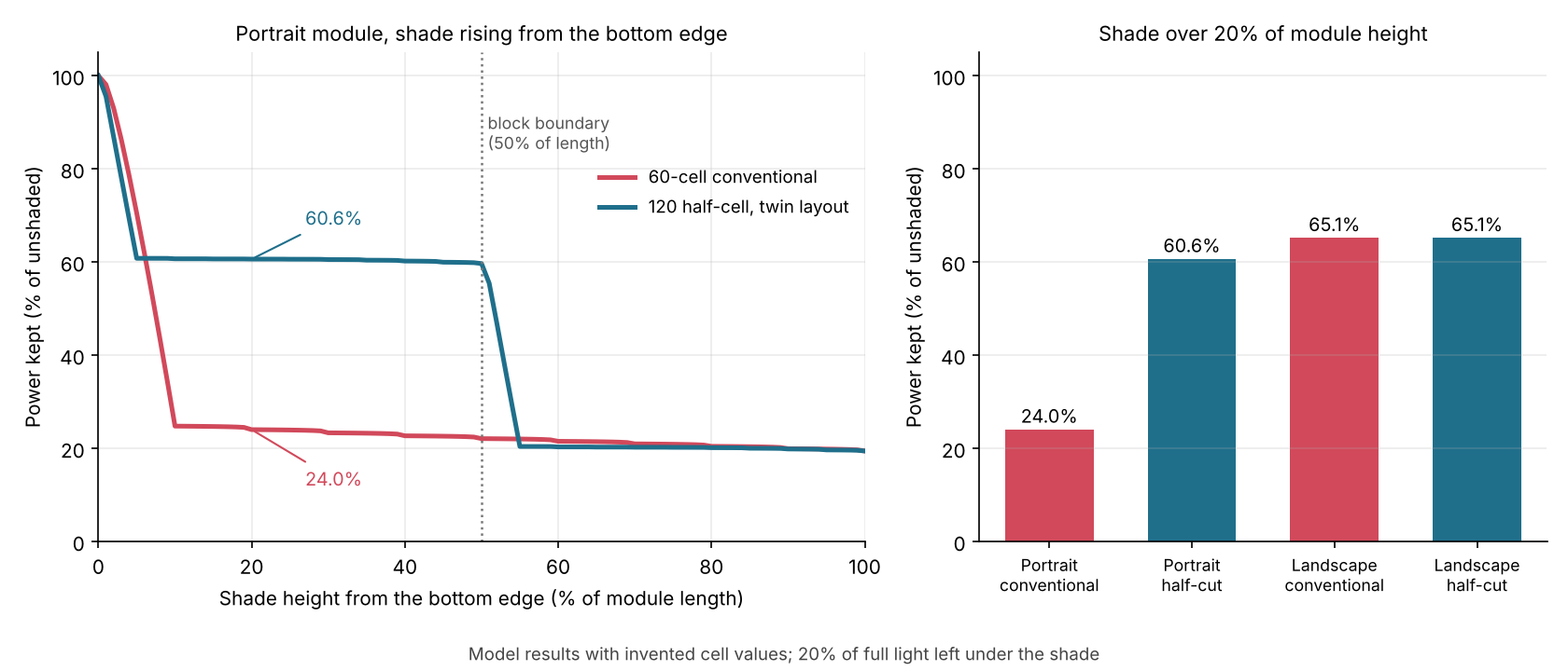
Figure 1. Shade over the bottom 20% of a portrait module leaves 60.6% of power with a twin half-cut layout and 24.0% with a conventional module (model, example cell values). Landscape modules keep 65.1% either way.
| Shade height from bottom edge | Portrait, conventional | Portrait, half-cut | Landscape, conventional | Landscape, half-cut |
|---|---|---|---|---|
| 10% | 24.8% | 60.7% | 65.1% | 65.1% |
| 20% | 24.0% | 60.6% | 65.1% | 65.1% |
| 40% | 22.7% | 60.2% | 49.8% | 49.8% |
| 60% | 21.5% | 20.3% | 30.3% | 30.3% |
In portrait, half-cut keeps far more power until the shade passes half the module length. In landscape both match.
Why portrait differs: bottom-edge shade touches every conventional substring. In the half-cut module it touches only the lower block, so the upper block keeps working. Past half the module length the shade reaches both blocks. The half-cut module keeps 1.2 points less at 60%. A thin strip of 5% height is different: the half-cut module keeps 60.8% and the conventional module keeps 70.5%. The strip covers a whole half-cell row but only half of each full-cell row, so the result depends on where the shade edge meets the cell rows.
Cross-checks: Klasen and others simulated a 60-cell conventional layout and a twin layout of the same cell area. For rectangular shading they report a shading resilience of 0.461 for the twin layout and 0.213 for the conventional one. Their metric is an average over many scenarios, so it differs from ours. The direction matches. The pvlib tracker example (row-to-row shading) also finds half-cut "performs better" in portrait. Our model has no reverse breakdown, so it shows no hot-spot heating. See bypass diode failure and mismatch loss.
Half-cut checker calculator
Our model shows how shade changes the result. Enter a shade height and remaining light, a tab loss, or a module’s Voc and cell count. Defaults reproduce the table above.
How do you read a half-cut cell count on a datasheet?
Treat the printed count as pieces, then find the series count. Module Voc divided by series cells should look like one cell’s Voc. None of these three sheets prints the series count. The table lists each sheet’s printed count, diodes and Voc, and the Voc per cell that follows.
| Item | Canadian Solar CS6R-420MS | Jinko JKM445N-54HL4R | REC Alpha Pure-R, 430 W |
|---|---|---|---|
| Cell wording | "Monokristallin". Header "HiKu6 Mono PERC" | "N type Mono-crystalline" | "80 half-cut bifacial REC heterojunction cells" |
| Printed count | 108 [2 x (9 x 6)] | 108 (2×54) | 80 |
| Word "half-cut" printed | No | No | Yes |
| Bypass diodes | 3 | Not stated | 4 |
| Voc at STC | 37.6 V | 39.59 V | 59.7 V |
| Voc per printed cell | 0.348 V | 0.367 V | 0.746 V |
| Voc if 54 in series | 0.696 V | 0.733 V | Not applicable |
A cell Voc near 0.35 V is about half what crystalline silicon cells give. Dullweber and others report 660 mV for a PERC cell, and n-type cells read higher. So 54 in series fits the first two sheets. That is our inference from the two-block layout and the Voc, not a printed figure. The REC figure of 0.746 V assumes all 80 cells in series. Only the maker can confirm the layout.
Tools differ on what they ask for. PVsyst’s twin half-cut page says to specify a "Twin half-cells" layout "with 60 (or 72) cells in series and 2 strings in parallel". For a 120 (or 144) half-cell module that means 60 (or 72). Size strings from the module Voc and Vmp as usual. See Voc and Isc and equipment datasheets.
How solar software handles half-cut layouts
Of the five tools read, only PVsyst documents twin half-cut cells with two parallel blocks. pvlib shows half-cut shading in a tracker example, HelioScope and Aurora document cell-string shading, and SAM has only a forum reply.
| Software | Documents half-cut layouts? |
|---|---|
| PVsyst | Yes |
| pvlib python | Partly |
| HelioScope | Partly |
| Aurora Solar | Partly |
| SAM | Not stated |
Not stated: the company page we cite does not say. Partly: the page covers cell-string shading or an example but does not name half-cut layouts. Page notes:
- PVsyst: "Since the version 7, the twin half-cut modules are fully implemented in the Module Layout construction." In landscape they "behave like standard modules". Page read: PVsyst help, Twin half-cut cells and shadings. No date shown, October 2026
- pvlib python: A single-axis tracker example (Martinez shade-loss model) compares half-cut modules with three bypass diodes: "half-cut cell modules are preferred in portrait orientation". Page read: pvlib 0.16.1 gallery, October 2026
- HelioScope: "HelioScope checks for shading on each cell string." It factors "the cell-structure of the module and the bypass diodes". Half-cut is not named on the page. Page read: Shade Modeling, "Updated" July 08, 2025 as printed. Read October 2026
- Aurora Solar: Aurora simulates "the actual cell string and bypass diode configuration of the module you’ve chosen". Its example is a 60 (72)-cell module with three strings. Half-cut is not named on the page. Page read: Submodule (Cell String)-Level Simulation, no date shown, October 2026
- SAM: A moderator’s forum reply (10 February 2020, SAM 2018.11.11) says the Detailed Photovoltaic model does not distinguish full-cell from half-cell modules. For the CEC user-entered option it advises whole cells in series. No SAM help page is cited. Page read: SAM forum thread, October 2026
To compare shading tools, see the best solar shading analysis software. For yield models, see the best solar simulation software.
Common mistakes with PERC and half-cut cells
FAQs
Is PERC the same as half-cut?
No. PERC describes the cell rear. Half-cut describes cell size and wiring. The REC sheet quoted here is half-cut and heterojunction, so half-cut is not a PERC feature.
Are half-cut panels better in shade?
Sometimes, mainly in portrait layouts. In our model a portrait twin module keeps 60.6% (model, example cell values) against 24.0% for shade over 20% of its height. In landscape both keep 65.1%, as PVsyst says. Run a shading analysis.
Do half-cut modules need different string sizing?
No. Size strings from the printed module Voc and Vmp, as for any module. The series count matters only in a module record, such as PVsyst’s. Check the maker’s wiring diagram when in doubt. See string sizing.
Is PERC obsolete?
No longer the leading cell type. pv magazine, reporting the ITRPV roadmap, says "TOPCon maintained its leading position in 2025, while p-type PERC continued to lose market share". TOPCon and HJT are covered on n-type, TOPCon and HJT. Which structure a given module uses is printed on its datasheet.
Related terms
- Solar cell: the single device that modules chain together.
- Bypass diode failure: what happens when a diode shorts or opens.
- N-type, TOPCon and HJT: the cell structures that follow PERC.
Next step: run a portrait and a landscape layout of your half-cut module through the best solar shading analysis software. For yield, use the best solar simulation software.
Sources
All sources checked October 2026. The IEC standard text is not cited.
- Papers and reports. Schneider and others, Fraunhofer CSP, Half-cell solar modules: the new standard in PV production?, Photovoltaics International, pp. 129-136 (no date printed). Singh and others, SERIS, Photovoltaics International, issue 113, pp. 114-120 (no date printed). Dullweber and others, The PERC+ cell, Photovoltaics International, issue 41, pp. 42-51 (no date printed). Klasen and others, Fraunhofer ISE, Quantitative Evaluation of the Shading Resilience of PV Modules (no venue in the text, file path 38th EU PVSEC 2021). Fokuhl and others, Fraunhofer ISE, LETID: a comparison of test methods on module level, 36th EU PVSEC, 2019.
- DOE, Crystalline Silicon Photovoltaics Research (published 24 January 2014, modified 17 December 2025).
- pv magazine, ITRPV global solar module shipments (25 June 2026), checked 30 October 2026.
- Datasheets, distributor copies: Canadian Solar HiKu6 CS6R-MS (German print), Jinko JKM425-445N-54HL4R and REC Alpha Pure-R US print (footer "UL EN 6.2025").
- Company and project pages (no dates shown unless stated). PVsyst, Twin half-cut cells and shadings. pvlib 0.16.1, Modelling shading losses in modules with bypass diodes. HelioScope, Shade Modeling (updated 8 July 2025 as printed). Aurora, Submodule (Cell String)-Level Simulation. SAM forum, Modeling half cells in SAM (10 February 2020).
Last updated 30 October 2026. Next scheduled review: 30 January 2027.