Key takeaways
- Scope runs from clearing and grubbing to fine grading, drainage and roads, and some sites need only a little.
- On a synthetic 6 ha site, a 1% plane falling south needs 47,810 m³ of cut and the same of fill at balance.
- An illustrative 10% shrink turns that balance into a 4,781 m³ import. Lowering the plane 8.4 cm restores it.
- On a known wedge, the grid method is exact when the zero line falls on a cell edge and reads a little low otherwise.
- On a synthetic 600 m road, average end area at 10 to 50 m stations lands within 1.7% of exact. At 100 m stations the error reaches 22%.
To see which design tools report cut and fill, see the best utility-scale solar design software.
Earthworks and grading at a glance
Earthworks is a volume problem. Cut is ground above the design surface. Fill is ground below it. The balance decides what trucks bring on or off site.
| Item | Detail |
|---|---|
| Formula | Volume = sum of (existing height minus design height) x cell area. Cut where positive, fill where negative |
| Unit | Cubic metres (or cubic yards), stated as bank, loose or compacted |
| Where it matters | Civil cost and schedule, tracker and racking tolerance, drainage, permits |
| Standard or rule | No single standard. Permit triggers, tolerances and shrink factors are set by regulator, maker and geotechnical report |
| In software | Layout tools report cut, fill and net. Civil tools offer grid, average end area and composite methods |
What does earthworks cover on a ground-mount site?
It covers every change to the ground before piles and trackers go in. This list is an editorial view of typical scope, not a standard.
- Clearing and grubbing. Pennsylvania DEP’s definition of earth disturbance includes "land clearing and grubbing".
- Bulk cut and fill to a design surface, as in the example below.
- Fine grading to tolerance. PVcase ties ground grading to the pile reveal length and clearing distance. RatedPower’s earthworks mode applies cut and fill to bring a north-south slope of 5 to 7% down to 5%. It also cuts terrain undulation to 100 cm.
- Drainage. Connecticut DEEP’s 2020 guidance says you should weigh panel orientation against the drainage pattern. It also says the hydrologic analysis must rest on the change in drainage patterns. We found no newer solar-specific DEEP guidance replacing it, but could not browse DEEP’s current site to confirm none exists. Check DEEP’s stormwater pages before relying on this.
- Access roads and pads for inverters, laydown and any substation. The tool pages do not describe road or pad grading.
- Compaction and restoration. Pennsylvania DEP says compacted areas count toward total earth disturbance.
Why earthworks drives cost and schedule
Trucks haul earth that must leave or enter the site. Regulators also scale erosion controls to the area disturbed.
Pennsylvania DEP says erosion and sediment controls must suit the size and scope of the project. The amount needed grows with the earth disturbance.
Permits follow the same logic. Under 25 Pa. Code § 102.5(a), earth disturbance of 1 acre or more needs an individual NPDES permit or coverage under a general one before work starts. Pennsylvania DEP’s guidance says it is not a regulation, so check the code text for your site.
Tolerance is the other driver. A tracker or racking model that cannot follow the ground forces grading. A terrain-following model may not. See single-axis trackers, racking design and terrain modelling, where you will find slope limits and the digital elevation model. Layout choices that avoid steep land also cut grading. See utility-scale layout optimisation and ground-mount design.
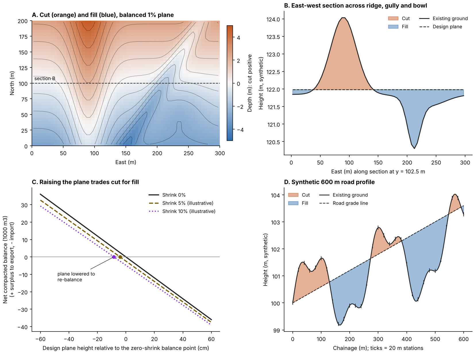
Figure 1. On our synthetic 6 ha site, raising the design plane trades cut for fill, and an illustrative 10% shrink moves the balance point down by 8.4 cm.
How are cut and fill volumes estimated?
Each method below is an estimate. Grid differencing subtracts two grids. Average end area averages the areas of cross-sections. The composite method uses the actual surface data between sections.
- Grid method (DEM differencing). In each cell, subtract the design height from the existing height and multiply by cell area. Then add up cuts and fills separately. Autodesk’s Civil 3D help says a grid volume surface "gives the exact difference only at the grid points".
- Average end area. Volume = (A1 + A2) / 2 x L for two sections L apart. Autodesk’s help says it suits sections of similar shape. LibreTexts’ Fundamentals of Transportation says the prismoidal formula removes most of its error.
- Composite method. Autodesk’s help says its composite method uses the actual surface data. It does not use formulas to fill in between sample lines.
A survey gives you the existing-ground grid. See lidar, drone photogrammetry (its image product is the orthomosaic) and site survey. You handle layers in GIS. Roads and pads belong on the site plan.
Swell and shrink. Trimble ProContractor’s help calls natural ground bank volume, excavated soil loose volume and compacted soil compacted volume. It applies "swell and yield factors" to convert between them. Per that page, swell converts bank to loose volume. Its yield factor converts loose to compacted volume. Its swell factors run 0.5 to 4.00. Its yield factors run 1.00 to 4.00.
The worked example below uses two simpler inputs, not Trimble’s factors. Shrink s means 1 m³ of bank cut gives (1 - s) m³ of compacted fill. Swell w means 1 m³ of bank soil occupies (1 + w) m³ loose. Take values from the geotechnical report.
Net balance in compacted m³ = cut x (1 - s) - fill. A surplus goes out. A shortfall comes in.
Worked example: balance, import and export
The surface is synthetic: 300 m by 200 m, 5 m cells (2,400 cells, 6.0 ha), ground from 118.79 to 125.74 m. It falls 1.8% to the south and has a ridge, a diagonal gully and a bowl. The target is an assumed plane falling 1.0% to the south with no east-west slope.
Higher shrink means a bigger import to hold the same plane.
| Case (plane height set from the zero-shrink balance) | Cut, bank m³ | Fill, compacted m³ | Net, compacted m³ | Import or export |
|---|---|---|---|---|
| Shrink 0% (illustrative) | 47,810 | 47,810 | 0 | None |
| Shrink 5% (illustrative) | 47,810 | 47,810 | -2,391 | Import 2,391 m³ compacted |
| Shrink 10% (illustrative) | 47,810 | 47,810 | -4,781 | Import 4,781 m³ compacted |
| Plane 20 cm lower. Shrink 10%, swell 20% (illustrative) | 54,119 | 42,119 | +6,588 | Export 7,320 m³ bank, 8,784 m³ loose |
The balancing plane height drops 4.1 cm at 5% shrink and 8.4 cm at 10%. A lower plane adds cut and removes fill. The deepest cut is 4.7 m and the deepest fill 4.2 m.
Cell size matters little on this smooth surface. Against a 0.5 m reference (47,822 m³ cut), 5 m cells read -0.02%. 10 m cells read -0.06% and 20 m cells -0.40%. Real ground has shorter features, so see the terrain page.
Test: a wedge with a known answer
The grid method is exact on a plane, so a wedge shows how much a straddled cell costs.
Take a 100 m by 60 m block. There, existing minus design height is d = a(x - x0), with a = 0.02. Cut is a(L - x0)²W/2 and fill is a x0²W/2. With x0 = 40 m that is 2,160 m³ and 960 m³.
| Zero line x0, cell size | Grid cut / fill, m³ | Analytical cut / fill, m³ | Error |
|---|---|---|---|
| 40 m, 5 m cells | 2,160 / 960 | 2,160 / 960 | 0.00% / 0.00% |
| 42.4 m, 5 m cells | 1,987.2 / 1,075.2 | 1,990.7 / 1,078.7 | -0.17% / -0.32% |
| 42.4 m, 1 m cells | 1,990.6 / 1,078.6 | 1,990.7 / 1,078.7 | -0.005% / -0.009% |
A cell that straddles the zero line takes the sign at its centre. So gross cut plus fill reads low. Net volume stays exact for a plane.
Test: a road profile, grid rule against average end area
Both rules stay close at short spacing and fail together at 100 m.
The road is synthetic: 600 m long with a 5 m formation. Its ground profile includes a component with a 90 m wavelength. We assumed 3H:1V side slopes and level ground across the width. There is no topsoil strip or pavement. Section area is (5 + 3h) x h for depth h. Exact volumes, by integration at 1 mm steps, are 1,338 m³ cut and 4,521 m³ fill. "Midpoint" is the grid-style rule: one section at the middle of each interval.
| Station spacing | Average end area cut, m³ (error) | Average end area fill, m³ (error) | Midpoint cut, m³ (error) | Midpoint fill, m³ (error) |
|---|---|---|---|---|
| 10 m | 1,335 (-0.22%) | 4,522 (+0.03%) | 1,342 (+0.24%) | 4,522 (+0.02%) |
| 20 m | 1,341 (+0.17%) | 4,543 (+0.51%) | 1,330 (-0.60%) | 4,501 (-0.44%) |
| 50 m | 1,317 (-1.61%) | 4,547 (+0.58%) | 1,283 (-4.13%) | 4,515 (-0.12%) |
| 100 m | 1,639 (+22.48%) | 3,918 (-13.34%) | 994 (-25.70%) | 5,176 (+14.51%) |
Neither rule errs in one direction. At 100 m spacing, the stations sit about as far apart as the 90 m wavelength in the road’s ground profile. Errors reach 22% for average end area and 26% for the midpoint rule. Keep stations close compared with the ground’s wavelength.
Cut and fill calculator
Part 1 takes a pasted grid of existing heights. It compares the grid with a design plane and applies your shrink and swell. It can also solve for the plane height that balances. Part 2 applies average end area to a station list. The sample data are the synthetic site at 20 m cells and the road at 20 m stations. They give the 20 m results, which differ slightly from the 5 m headline table. A 5 m grid is not included, so that table cannot be reproduced there.
How solar software handles earthworks
PVcase Ground Mount, RatedPower, PVFARM and Autodesk’s civil tool document cut and fill volumes. Only Trimble ProContractor documents swell and yield factors. A tool that reports net volume should also say how it builds the design surface.
| Software | Cut, fill and net? | Swell or shrink factors? | Page read |
|---|---|---|---|
| PVcase Ground Mount | Yes | Not stated | PVcase help, fixed-tilt grading (stamp 8 January 2026) and single-axis grading (updated 23 July 2025) |
| RatedPower | Yes | Not stated | RatedPower knowledge base, undated (URL moved since October 2026, check RatedPower’s current help centre) |
| PVFARM | Yes | Not stated | PVFARM success centre, "How cut and fill works", undated (2026 copyright) |
| Autodesk Civil 3D | Yes | Not stated | Autodesk help, 2024 sectional and grid pages. Metadata dates conflict |
| Trimble ProContractor | Not stated | Yes | Trimble help, modified 7 September 2026 |
Where a cell says "Not stated", the pages read do not state it.
- PVcase Ground Mount: grading summary with cut, fill and net volumes. Grading driven by pile reveal length and clearing distance. Fixed-tilt page says the Area grade section shows how much was cut, filled and the net. Roads and pads not mentioned.
- RatedPower: earthworks mode applies cut and fill to reduce a north-south slope of 5 to 7% to 5% (steeper structures are removed). Total cut and fill go into the Design Report and BOQ. Roads and platforms not addressed.
- PVFARM: optimisation minimises cut plus fill within a boundary. Cut minus fill is set to the net balance you choose. Volume is the difference between the original and optimised surface. Roads not mentioned.
- Autodesk: grid volume surface, with cut, fill and net viewable in Surface Properties. Sectional methods: average end area, prismoidal and composite. General civil tool, not solar-specific.
- Trimble ProContractor: swell and yield factors in an estimating tool for contractors. The Trimble page does not describe surface differencing.
For more tools that report cut and fill on utility-scale sites, see the best utility-scale solar design software list.
Common mistakes with earthworks estimates
FAQs
How do you calculate cut and fill?
Subtract the design height from the existing height at each grid cell. Positive differences are cut. Negative ones are fill. Multiply by cell area and add up each. In our wedge test this gave the exact volume when the zero line sat on a cell edge.
What is the difference between bank, loose and compacted volume?
Bank volume is natural ground, loose volume is excavated soil and compacted volume is soil after compaction. Trimble ProContractor’s help uses these terms and converts between them with factors. Factors depend on the soil.
Does every solar site need grading?
No. Pennsylvania DEP says some sites may need a lot of grading, including clearing and grubbing. Others may need only limited disturbance to grade the ground evenly. The amount depends on slope, tracker tolerance and drainage.
Is average end area or the grid method more accurate?
Neither always wins. On our synthetic road both were within 4.2% at 10 to 50 m spacing and both failed at 100 m. Accuracy depends on station spacing compared with the ground’s wavelength, and on how often cut and fill alternate.
How much does earthworks cost on a solar farm?
No sourced benchmark was found, so this page gives no price. Cost follows the net import or export in cubic metres and the shrink basis, as in the worked example. Price your own volumes with a quote.
Related terms
- Topography and terrain modelling: slope, aspect and the digital elevation model.
- Ground-mount design: tilt, row pitch, foundations and grading in one plan.
- Cable routing and trenching: the other ground-disturbing work.
Next step: test your own grid in the calculator above, then see the best utility-scale solar design software that reports cut and fill.
Sources
- Pennsylvania DEP, Solar Panel Projects FAQ, version 1.3, revised 19 February 2026 (checked October 2026). It says its interpretations are not a regulation.
- Cornell LII, 25 Pa. Code § 102.5, Permit requirements (checked 30 October 2026, not the official code site).
- Connecticut DEEP, guidance for construction of solar array projects, 8 January 2020 (checked October 2026).
- Autodesk Civil 3D, About Analyzing Sectional Volumes and About Creating a Grid Volume Surface (page metadata shows conflicting dates, checked October 2026).
- Levinson et al., Fundamentals of Transportation, 7.3 Earthwork, Engineering LibreTexts, last modified 30 April 2021 (checked October 2026).
- Trimble ProContractor help, Enter Swell and Yield Factors, modified 7 September 2026 (checked October 2026).
- PVcase help, Civil analysis: Ground grading (Fixed-tilt) and single-axis trackers (updated 23 July 2025, checked October 2026).
- RatedPower knowledge base, topography limitation and earthworks tool (undated, checked October 2026, this URL now redirects to a page that returns a 404, re-checked 3 November 2026).
- PVFARM, How cut and fill works (undated, checked October 2026).
Last updated 30 October 2026. Next scheduled review: 30 January 2027.