Key takeaways
- Example only: a DJI Mavic 3E wide camera at an assumed 80 m gives 2.13 cm per pixel. A 10 ha site needs 140 photos.
- For dense vegetation, Pix4D says to use at least 85% overlap, above its general-case minimum.
- Resolution is not accuracy. Pix4D says absolute accuracy cannot be higher than the accuracy of image geolocation or of the ground control points.
- In our example, a 10 m tall object near the photo corner is shifted 8.8 m in the raw image. A height model undoes this.
- If the ground rises 15 m (assumed), planned 75% and 60% overlap fall to 69% and 51% at the highest point.
To import a drone map into a design, see the best solar roof measurement software. If you fly your own maps, see the best solar drone inspection software. Aurora Solar and Scanifly are rated Partly in the software table below.
Orthomosaic at a glance
An orthomosaic is a measurable map made from photos. Software corrects each photo for tilt and height, then joins the corrected images.
| Item | Detail |
|---|---|
| Formula | GSD = pixel pitch × flight height ÷ focal length. Photo spacing = footprint × (1 − overlap) |
| Unit and typical range | GSD in cm per pixel. No sourced typical range is given, so the page gives a worked example |
| Where it matters | Site plan, array layout, as-built record, inspection base map |
| Standard | No single standard in the sources read. Accuracy depends on control and processing |
| In software | Photogrammetry tools make it. Design tools may import it as an image |
Why does an orthomosaic matter for installers?
It gives you a current, to-scale picture of the site. You can plan and check work before and after construction.
DroneDeploy’s renewable energy page says its tool can "produce high-accuracy orthos and 3D models for design and as-builts". A site plan or solar panel layout drawn on an old or skewed image can misplace arrays and keep-out zones.
Scanifly’s blog, a company view, says satellite images can be skewed or old. Check the date of any image. See aerial imagery for other sources.
How is an orthomosaic different from a photo, a DSM and a point cloud?
A photo has perspective, so scale changes across it. An orthomosaic has uniform scale. A DSM and a point cloud carry height. An orthomosaic does not.
| Product | What it is | Use it for | Source |
|---|---|---|---|
| Normal photo | Central perspective: scale and position shift with height, tilt and distance | Context and evidence | USACE EM 1110-1-1000, chapter 10 |
| Orthophoto | A photo with "the effects of central perspective, relief displacement, and tilt (practically) removed" | Measuring distances on a flat map | USACE, 31 March 1993 |
| Orthomosaic | Orthophotos stitched into one map. Pix4D: "a highly detailed and realistic 2D representation of reality", built from the DSM and the images | Site plan, layout backdrop, as-built record | PIX4Dmatic help |
| DSM | "A 2D representation of elevation" (Pix4D) | Heights of ground and objects | PIX4Dmatic help |
| Dense point cloud | "A collection of points distributed throughout a 3D space" (Pix4D) | 3D checks, volumes, terrain modelling | PIX4Dmatic help |
An orthomosaic is a map, not a height model. Take heights from a DSM or a point cloud, or from LiDAR. ITC lecture slides link a true orthophoto, with building tilt removed, to a DSM.
How is an orthomosaic made?
You fly overlapping photos and tie them to known coordinates. Then photogrammetry software builds a height model and the map.
- Pick the GSD the job needs. Pix4D says the required GSD "will define the distance (flight height)".
- Fly a grid with overlap. Pix4D’s PIX4Dmapper guidance gives a general-case minimum of 75% frontal and 60% side.
- Tie the images to coordinates with an RTK or PPK drone, ground control points (GCPs), or both. Add checkpoints that the software does not use.
- Process the images. The software builds a dense point cloud and a DSM, then the orthomosaic from the DSM and the images.
- Export, for example as GeoTIFF, and check the result against the checkpoints. The next sections explain the checks. For the survey side, see drone site survey and photogrammetry.
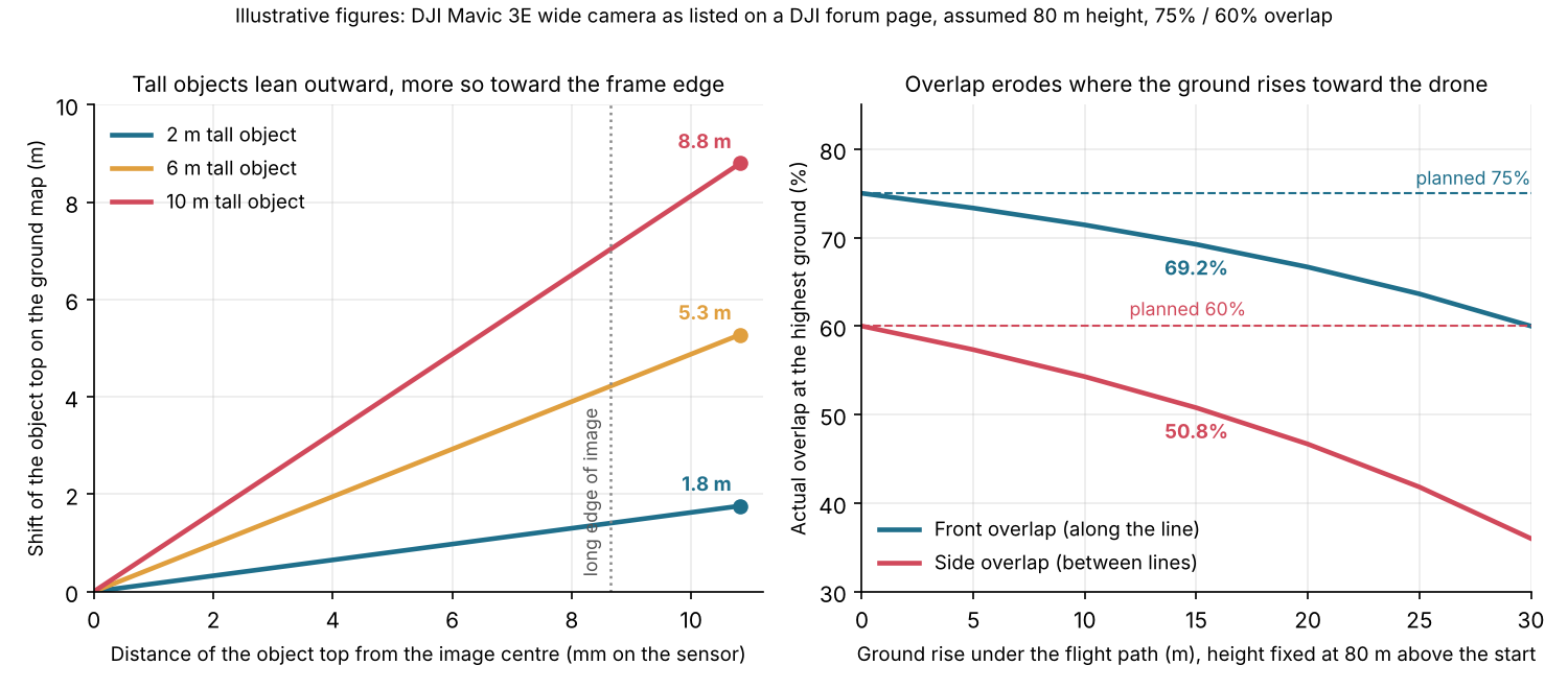
Figure 1. In our example, object tops shift outward in proportion to height and distance from the image centre. A 15 m ground rise cuts planned overlap to 69% and 51%.
Worked example: GSD, footprint and photo count
For this camera at an assumed 80 m height, GSD is 2.13 cm per pixel and the example site needs 140 photos. Every input below is an assumption unless a source is named.
| Input | Value and basis |
|---|---|
| Camera | DJI Mavic 3E wide camera: sensor 17.3 × 13 mm, lens 12.3 mm, 5280 × 3956 pixels (DJI developer forum, no date printed) |
| Pixel pitch | 17.3 mm ÷ 5280 = 3.28 µm (our calculation, the page lists no pixel size) |
| Flight height | 80 m above ground (assumed) |
| Overlap | 75% front, 60% side (Pix4D general-case minimum, chosen as the plan) |
| Site and lines | 400 m × 250 m = 10 ha (assumed). Lines run along the 400 m side. The long image side lies across the lines (assumed) |
- GSD = 3.28 µm × 80 m ÷ 12.3 mm = 2.13 cm per pixel.
- Footprint = pixels × GSD: 5280 × 2.13 cm = 112.5 m across, 3956 × 2.13 cm = 84.3 m along.
- Photo spacing along the line = 84.3 × (1 − 0.75) = 21.1 m. Line spacing = 112.5 × (1 − 0.60) = 45.0 m.
- Lines = round up (250 ÷ 45.0) + 1 = 7. Photos per line = round up (400 ÷ 21.1) + 1 = 20. Total = 7 × 20 = 140 photos.
The extra line and photo give the site edge the planned overlap. That margin is our choice, and software may differ. That DJI forum page also lists 12.29 mm for the Mavic 3M. That would change GSD by 0.08%, which does not alter these figures.
Now add terrain. Say the ground rises 15 m under the flight path and the drone holds 80 m above the start. At the high point the drone is 65 m above ground. GSD falls to 1.73 cm and the footprint shrinks to 91.4 m by 68.5 m. Overlap drops to 69.2% front and 50.8% side. Both are below Pix4D’s minimum. Pix4D says to adjust flight height and overlap for the terrain. Fly higher, or follow the terrain.
Why does orthorectification matter? Relief displacement
In a vertical photo, anything above the ground plane looks shifted outward from the image centre. The shift grows with height and with distance from the centre.
Formula: d = r × h ÷ H. Here d is the shift in the image. r is the radial distance from the image centre to the object top. h is the object height. H is the flying height above the object’s base. The USACE chapter prints d = rh/H. The Oldenburg SEOS teaching page gives the same relation and defines h and H. Both assume a vertical photo.
| Object height | Long image edge (35° off vertical) | Image corner (41° off vertical) |
|---|---|---|
| 2 m | 1.41 m (66 pixels) | 1.76 m (83 pixels) |
| 6 m | 4.22 m (198 pixels) | 5.28 m (248 pixels) |
| 10 m | 7.03 m (330 pixels) | 8.80 m (413 pixels) |
Rule of thumb: the shift is the object height times the tangent of the angle off the vertical. On the ground plane that equals r × h ÷ f, where f is the focal length. It is zero at the image centre and points away from it.
The table assumes the same camera, 80 m height above the object’s base, a vertical photo and a flat plane.
Suppose a mosaic used only the centre of the nearest photo for each ground point. The worst offset in our grid would then be 24.8 m (17° off vertical). By the rule of thumb above, a 10 m object would lean about 3.1 m (10 m × tan 17°). Choosing the nearest centre is our assumption. Real software may blend seams differently.
Orthorectification uses a height model to undo the shift. The ITC slides say errors in the height model leave some displacement in the orthophoto. A thin pole or wire is a likely case. Check the DSM before you trace a roof edge or a tall obstruction. See keep-out zones.
Orthomosaic flight planner calculator
Enter your camera, height, overlap and site. It returns GSD, footprint, spacing, photo count, overlap at the highest ground and the shift of an object top. It rejects impossible inputs and warns when overlap is below the general-case minimum. It is a planning aid, not a flight plan.
What decides an orthomosaic’s accuracy?
Control decides absolute accuracy. GSD sets how small a feature you can see, not how well the map sits in real coordinates.
- Georeferencing: Pix4D says "the absolute accuracy of the results cannot be higher than the accuracy of image geolocation, or GCPs’ accuracy". It adds that GCPs or RTK and PPK drones can greatly improve absolute accuracy.
- Standard GPS: Wingtra describes standalone GPS-grade accuracy as "a few meters". GCPs are meant to improve on that when data is not RTK or PPK corrected.
- Control points: DroneDeploy’s help says at least 4 GCPs are required without RTK or PPK. For RTK or PPK work with no GCPs it recommends at least 1 to 2 checkpoints.
- Company limits: Aurora’s drone mapping help says to treat its mesh as "a strong visual reference, not a survey-grade measurement". No company figure is quoted as a typical accuracy, so the page gives none.
How solar software handles orthomosaics
On the pages we read in October 2026, only Pix4D documents orthomosaic output in full. DroneDeploy, Aurora Solar and Scanifly document it in part.
| Software | Documents orthomosaic output? | Source and date |
|---|---|---|
| Pix4D | Yes | Orthomosaic and Quick Start help pages. No date printed, copyright 2026. Read October 2026. |
| DroneDeploy | Partly | Solutions page, no date printed. GCP help updated 24 March 2026. Read October 2026. |
| Aurora Solar | Partly | Drone Mapping help, stamped 1 October 2026. Read October 2026. |
| Scanifly | Partly | Blog published 26 September 2023, modified 29 April 2025. Product page modified 24 June 2026. Read October 2026. |
| PVcase Ground Mount | Not stated | Help page updated 12 October 2026. Product blog 24 March 2025. Read October 2026. |
Not stated: neither page we read mentions orthomosaics. Partly: the pages cover drone maps or orthos only in part. What each page says:
- Pix4D: the help page says "Create an orthomosaic based on the digital surface model (DSM) and the images." Exports JPG, GeoTIFF and KML.
- DroneDeploy: the solutions page names "orthos and 3D models for design and as-builts". The help pages read cover ground control, not how the orthomosaic is built.
- Aurora Solar: builds a custom LIDAR source, a 3D mesh and a scaled top-down image from raw JPG drone images. Accepts a drone map orthophoto (GeoTIFF) as a custom image. Build, Grow and Scale plans only. The page does not use the word orthomosaic.
- Scanifly: a company blog describes stitching, georeferencing and orthorectifying photos. The product page read does not mention orthomosaics.
- PVcase Ground Mount: the Topography compatibility help page covers terrain survey data in DWG format.
Our terrain modelling page rates PVcase’s terrain layout separately. For tools that build or use drone maps, see the best solar drone inspection software and the best solar roof measurement software.
Common mistakes with orthomosaics
FAQs
Is an orthomosaic the same as an orthophoto?
Nearly. An orthophoto is one orthorectified image with uniform scale (ITC slides). An orthomosaic joins many. DJI’s enterprise blog (28 July 2021) lists orthophoto as another name.
Do I need GCPs if my drone has RTK?
Fewer, possibly none, but keep checkpoints. For RTK or PPK work with no GCPs, DroneDeploy recommends at least 1 to 2 checkpoints. Wingtra says you "may not need any" GCPs with reliable equipment.
Can I use an orthomosaic instead of satellite imagery?
Yes, when you can fly the site. An orthomosaic is as current as your last flight, but it costs a flight and needs control points. Satellite or aerial imagery can suit early designs. See aerial imagery and GIS for layers and coordinates.
What overlap should I fly?
Fly at least 75% frontal and 60% side overlap for general cases. Use more for dense vegetation. Check overlap where the ground rises, because the footprint shrinks. Adjust flight height and overlap for the terrain.
Is an orthomosaic survey grade?
Not by default. Absolute accuracy cannot be higher than the accuracy of image geolocation or the GCPs. Aurora calls its mesh "a strong visual reference, not a survey-grade measurement". Use control points and checkpoints.
Related terms
- Drone site survey / photogrammetry: flying a site and building maps and models from the photos.
- Aerial imagery: top-down images from aircraft or satellites.
- Drone inspection: thermal and visual flights over a plant, with their own resolution rules.
Next step: to turn drone photos into a design backdrop, see the best solar roof measurement software. For inspection flights, see the best solar drone inspection software.
Sources
All pages were opened in October 2026.
- US Army Corps of Engineers, EM 1110-1-1000, chapter 10, Principles of Photogrammetry (31 March 1993).
- SEOS project, relief displacement (no date printed).
- ITC, Orthophoto and Orthomosaic lecture slides (no date printed).
- Pix4D, Image acquisition and What is the relative and absolute accuracy of drone mapping? (no dates printed).
- Pix4D, Quick Start Guide PIX4Dmatic and Orthomosaic - PIX4Dmatic (no dates printed).
- DJI developer forum, custom camera parameters for the Mavic 3 Enterprise series (no date printed).
- DroneDeploy, Best Practices for GCPs and Checkpoints (updated 24 March 2026) and DroneDeploy, renewable energy (no date printed).
- Aurora Solar help, Drone Mapping (stamped 1 October 2026).
- Scanifly, What’s an orthomosaic map (26 September 2023, modified 29 April 2025) and Scanifly PV design (modified 24 June 2026).
- PVcase help, Topography compatibility (updated 12 October 2026) and PVcase spring product updates (24 March 2025).
- Wingtra, Ground control points guide (dated 15 October 2026) and DJI Enterprise, Making orthomosaics with drones (28 July 2021).
Last updated 30 October 2026. Next scheduled review: 30 January 2027.