Key takeaways
- The box holds terminals, bypass diodes, a seal and the cable leads. IEC 62790:2020 covers boxes up to 1,500 V DC. The catalogue scope text gives no current limit.
- IP68 is not one test. TE’s page says 1 m for 24 hours, and Amphenol’s says 1 m for 1 hour, mated.
- For an example 14.0 A module with 10% rear gain, the current to compare is 15.4 A. A printed 15 A rating falls short. A 17 A rating and a 25 A rating pass.
- The lowest rating in the chain sets the limit. A 25 A box with a 35 A connector is a 25 A part.
- Stäubli says its MC4 connectors "may not be mated with products from other PV connector manufacturers".
To find hot junction boxes on site, see the best solar thermal inspection software.
Junction box at a glance
The junction box is the connection point on the back of a PV module. Its printed ratings matter when you compare modules or replacement parts.
| Item | Detail |
|---|---|
| Where | On the back of the module. It joins the cell substrings to the positive and negative output cables. |
| Usually inside | Terminals, bypass diodes, a seal and the cable leads with connectors. See what is inside. |
| Ratings printed | Current, voltage, IP code and temperature range. See the ratings table. |
| Standard or rule | IEC 62790:2020 (up to 1,500 V DC, class II). UL 3730 for US listings. The standard texts are not quoted here. See Sources. |
| In software | Module libraries store the diode count. Inspection tools can flag a hot junction box. See the software table. |
Why the junction box matters for installers
This small part carries the module’s full output current and holds its diodes. Its ratings, connectors and heat behaviour affect buying, installing and O&M.
- Buying: makers word current, voltage and IP ratings differently. Compare the test conditions, not only the codes. See equipment datasheets.
- Installing: the leads end in connectors. Connector makers set their own mating rules.
- O&M: a thermal image can show heat at the box. See thermal inspection and bypass diode failure. For tools that flag a hot box, see the best solar thermal inspection software.
What is inside a junction box?
A module junction box holds terminals for the cell ribbons, bypass diodes, a seal and the output leads with connectors. Designs differ. These two company pages show how.
| Part | What the pages say |
|---|---|
| Ribbon terminals | Amphenol Saguaro: "Number of terminals: 3", flat wire size "≤ 7 mm", sealed by "Potting". |
| Bypass diodes | Amphenol’s box lists a 40 A, 45 V diode. PVsyst puts 3 diodes on 60- and 72-cell modules and 4 on 96-cell. |
| Seal | Amphenol seals with potting. TE says "no potting necessary". |
| Leads and connectors | Amphenol: H4 Plus connector rated "35 A". TE: an "integrated PV4-S interface". |
| Enclosure | Amphenol: 63.5 x 28 x 14.5 mm, flammability "5VA, Safety Class II". |
- Bypass diodes: Amphenol’s diode entry lists "Average Rectified Output Current: 40 A" and "Peak Reverse Voltage: 45 V" (MK4045 option). TE puts the diode "in a separate compartment" for better heat transfer in shading.
- Diode count: the PVsyst help page says "Normally 3 diodes for 60 and 72 cells, 4 diodes for 96 cells in series". That is 20, 24 and 24 cells per diode (division by this page).
- Temperatures: Amphenol lists connector -40 to 85 °C, wire -40 to 90 °C and diode -55 to 200 °C.
TE’s range is titled "decentralized junction boxes", so check the module sheet for the box count. For diode failure modes, see the bypass diode failure page. For cell layouts, see PERC and half-cut cells.
What do the ratings and standards on a junction box mean?
Three printed items matter: rated current, rated voltage and the IP code. Read the test wording next to each. It differs by maker.
| Item | TE SOLARLOK PV Edge (Mouser page) | Amphenol Saguaro (company page) |
|---|---|---|
| Current | "15A (standard version)". "17A" special version | Box "25A". H4 Plus connector "35 A" |
| Voltage | "1500VDC withstanding voltage" | "1500V DC" |
| IP code and test | "IP68 ... waterproof protection at 1m for 24 hours" | "IP68 (1 meter, 1 hour, mated)" |
| Standards named | "pure IEC- and UL-approved 1500V solution" | "UL 3730 / IEC 62790". The page also says certification is "in process" |
| Page date | Published 2019-01-22, updated 2023-09-18 | Metadata 2026-08-31, no revision |
Ratings can differ by part number, so the sheet for the exact variant is the one that counts.
- IEC 62790:2020: VDE Verlag’s catalogue says it "describes safety requirements, constructional requirements and tests for junction boxes up to 1 500 V DC". The boxes are for modules "in accordance with class II of IEC 61140:2016". It replaces the 2014 first edition. The scope also covers enclosures with electronics but leaves those circuits to other standards.
- UL 3730: InCompliance says it covers boxes "intended for factory and field wiring". They "may include conduit openings, wiring leads, and/or photovoltaic connectors".
- IP68: Bopla’s explainer of IEC 60529 says dust "must not enter at all". Water must not enter "in a quantity that could have harmful effects" under immersion, with depth and time set by the maker and user. See IP rating.
- Test routine: TÜV Rheinland’s check routine for the 2014 edition (IEC/EN 62790:2014) lists a thermal cycle test at rated current, 200 cycles from -40 to +85 °C. Its bypass diode test holds (75 ± 5) °C at rated current for 1 hour, then "1,25 times value of rated current" for 1 hour. It gives a minimum of IP55.
- Connectors: Stäubli’s statement of 25 March 2021 lists IEC 62852:2014+A1:2020 and UL 6703 among the standards it cites.
Worked check: does the printed rating fit the module?
Take the module’s current, including any rear-side gain. Compare it with the lowest current rating in the chain. This check compares printed numbers. It is not the maker’s design rule or a code calculation.
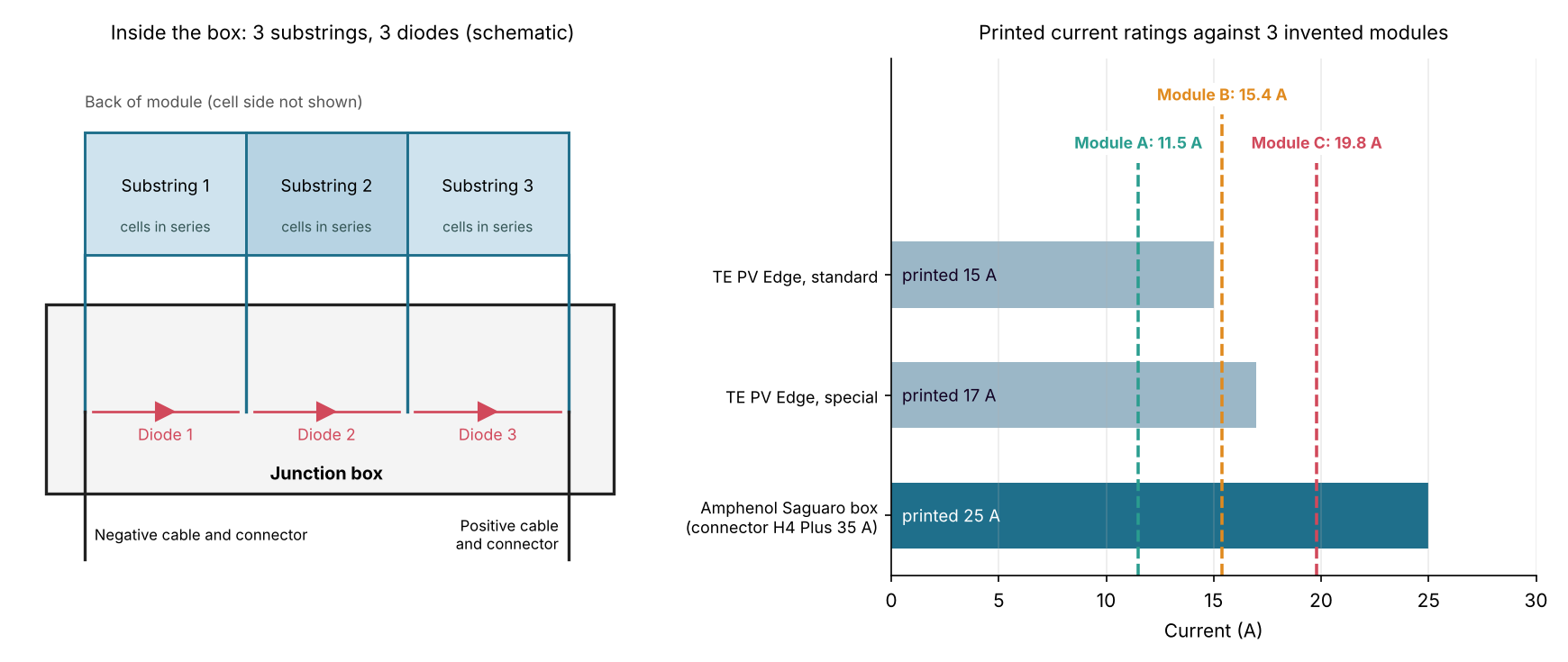
Figure 1. A 15 A printed rating is below an example 14.0 A module with 10% rear gain (15.4 A). A 17 A rating clears it. A 25 A box with a 35 A connector is limited to 25 A.
Method: current to compare = Isc × (1 + rear gain). Divide the lowest printed rating by it. A result below 1.00 means the rating is lower than the module current. Module values are example. Ratings are those in the table above.
| Example module | Isc | Rear gain | Current to compare |
|---|---|---|---|
| Module A | 11.5 A | 0% | 11.5 A |
| Module B | 14.0 A | 10% | 15.4 A |
| Module C | 18.0 A | 10% | 19.8 A |
The second table shows whether each printed rating is at or above that current, with the rating divided by the current in brackets.
| Example module | TE 15 A | TE 17 A | Amphenol 25 A box, 35 A connector |
|---|---|---|---|
| Module A | Yes (1.30) | Yes (1.48) | Yes (2.17) |
| Module B | No (0.97) | Yes (1.10) | Yes (1.62) |
| Module C | No (0.76) | No (0.86) | Yes (1.26) |
Module C shows that the lowest rating rules. The box says 25 A and the connector 35 A, so 25 A applies. Module makers pick the box for the module. Use this check to compare datasheets and parts. Do not use it to approve a swap.
Rating check calculator
If the calculator does not load, Open the junction box rating check calculator on its own page.
What goes wrong at the junction box?
In one NREL laboratory test, 7 of 36 c-Si boxes failed an adhesion test after 1,000 hours of damp heat. Other sources describe heat and connector problems, but none gives field failure rates.
- Moisture and adhesion: Miller and Wohlgemuth (NREL preprint on a junction-box adhesion test, August 2012) name "moisture ingress, subsequent corrosion, and the corresponding loss of performance" as risks. In their damp-heat tests (85 °C, 85% relative humidity), 7 of 36 c-Si specimens failed the weighted adhesion test after 1,000 hours. The paper’s 17 of 42 figure sits under its thin-film results section. These are laboratory samples, not field rates. The authors also say cable glands "are typically not designed to support a substantial sustained load".
- Connectors: Kalejs, Gadomski and Nobel (NREL workshop presentation, 26-27 February 2013) report a melted joint. They also report a 2-3 mm gap between mating connectors after 2-4 years in the field. They list mixing parts from different makers as a possible issue. They give no statistics.
- Heat: a warm box can be normal or a fault. Miller and Wohlgemuth list "activation of the by-pass diodes and high temperature at the j-box" among hot-spot conditions. See anomaly classification.
Junction box, combiner box or diode failure: which is which?
The junction box sits on the module. A combiner box joins strings later. Diode failure is a fault inside the junction box.
| Term | Where | What it does | Page |
|---|---|---|---|
| Junction box | Back of the module | Joins substrings to the output cables. Holds bypass diodes | This page |
| Combiner box | After the strings | Joins string circuits into one protected DC output | Combiner box |
| Bypass diode failure | Inside the junction box | A diode that no longer works as designed | Bypass diode failure |
Some designs add electronics. A 2016 Sunage and Tigo press release says the Tigo TS4 "replaces the traditional JBox". Tigo’s support page also covers its legacy integrated J-box. IEC 62790 covers enclosures that contain electronics too. See MLPE, power optimisers and module-level monitoring.
How solar software handles the junction box
Only Raptor Maps and Sitemark document a named junction-box finding. PVsyst stores just the diode count. The table shows what each page names, and the bullets under it carry the company wording.
| Software | Junction-box content documented? | Method | Source and date |
|---|---|---|---|
| Raptor Maps | Yes | Remote thermal | Anomaly glossary, copyright 2025. October 2026 |
| Sitemark | Yes | Remote thermal | Help page, date stamp 22 September 2026. October 2026 |
| PVsyst | Partly | Modelled | Help page, no date shown. October 2026 |
- Raptor Maps: Defines a junction box as "an enclosure on the module that connects the PV strings". A junction-box anomaly is "a hot spot at the junction-box location on the module". Severity runs from low (under 10 °C above adjacent areas) through medium (10-20 °C) to high (20 °C higher than adjacent areas). The wording puts 20 °C in both medium and high.
- Sitemark: Lists a "Heated Junction Box" anomaly type. It says junction boxes are expected to run slightly warm. It says assessment is mainly relative to neighbouring modules. It also says a high temperature may indicate connection issues causing power losses or a fire hazard.
- PVsyst: The module form has "Nb of bypass diodes", "Useful for the electrical shading calculations in the Module Layout part". The page does not mention a junction box.
Partly: PVsyst stores only the diode count. Sitemark names its finding but states no repair action.
For tools that find hot junction boxes on site, read the best solar thermal inspection software list. For fleet-wide fault tracking, see the best solar performance analytics software list.
Common mistakes with junction boxes
FAQs
How many bypass diodes are in a junction box?
Often 3 or 4, but the datasheet decides. The PVsyst quote in the parts table gives 3 or 4 by cell count. Amphenol’s page for its 3-terminal box does not state a diode count.
Is a junction box the same as a combiner box?
No. The junction box is on the module and joins its substrings to the output cables. A combiner box is a separate enclosure that joins string circuits. See combiner box.
Can you replace a failed junction box?
Only where the maker documents it. Tigo’s support page says each version of its legacy integrated J-box "is removable and field replaceable". The pages read give no maker guidance for other modules. The module maker can advise on warranty and safety first.
Why does a junction box look hot in a thermal image?
A hot box can mean an active bypass diode or a poor connection. Raptor Maps grades a junction-box hot spot by temperature above adjacent areas. Sitemark says boxes are expected to run slightly warm. It judges them mainly against neighbours. Confirm a hot box with an electrical test.
Related terms
- Solar panel (module): the unit that carries the junction box.
- Bypass diode failure: how the diodes in the box fail and how to find them.
- IP rating: the dust and water protection code printed on the box.
Next step: scan a site for hot boxes with the best solar thermal inspection software, or track faults fleet-wide with the best solar performance analytics software.
Sources
All sources checked October 2026. The IEC and UL scope lines come from the catalogue and article pages below, not from the standards.
- Standards and listings: TÜV Rheinland, check routine for IEC/EN 62790:2014 (undated). IEC 62790:2020, VDE Verlag. EN IEC 62790:2020, EVS. UL 3730 article, InCompliance. IP68, Bopla.
- Companies: Amphenol Saguaro Junction Box. TE SOLARLOK PV Edge, Mouser. Stäubli connector statement, 25 March 2021. Tigo support, legacy J-boxes. Sunage and Tigo press release, 24 February 2016.
- Research: Miller and Wohlgemuth, NREL/CP-5200-54185, August 2012 (preprint, link moved to the nlr.gov domain after the lab’s 2025 rename, re-verified November 2026). Kalejs, Gadomski and Nobel, NREL PV Module Reliability Workshop, February 2013, via DOE (presentation, not peer reviewed).
- Software: Raptor Maps anomaly glossary. Sitemark thermal anomaly types. PVsyst, PV modules main interface.
Last updated 30 October 2026. Next scheduled review: 30 January 2027.